
Encoding apparatus and encoding method, and decoding apparatus and decoding method

Inactive Publication Date: 2021-05-06
CANON KK
View PDF0 Cites 0 Cited by
  • Summary
  • Abstract
  • Description
  • Claims
  • Application Information

AI Technical Summary

Benefits of technology

The patent text describes a way to make image data, like RAW images, smaller without losing quality. The invention aims to improve the compression rate of image data while reducing the impact on image quality. The technical effect is better quality image data that is smaller in size.

Problems solved by technology

RAW image data is not suitable for display as is.
However, such a conversion often includes lossy image processing that may degrade image quality, in order to reduce the data amount, for example.
Data amounts of RAW image data have become very large as the number of pixels of an image sensor increases.

Method used


Image

  • Encoding apparatus and encoding method, and decoding apparatus and decoding method
  • Encoding apparatus and encoding method, and decoding apparatus and decoding method
  • Encoding apparatus and encoding method, and decoding apparatus and decoding method

Examples


first embodiment

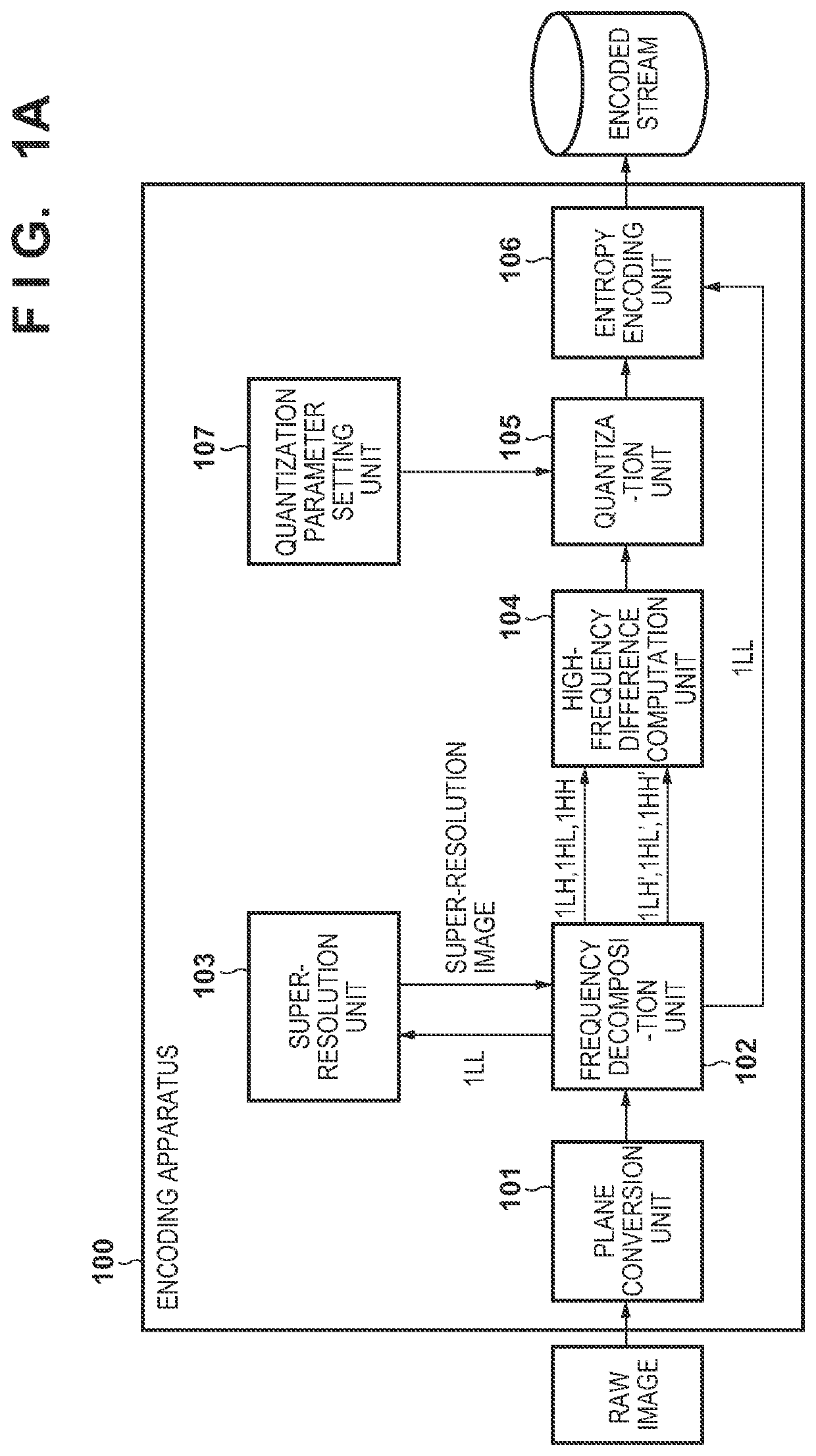
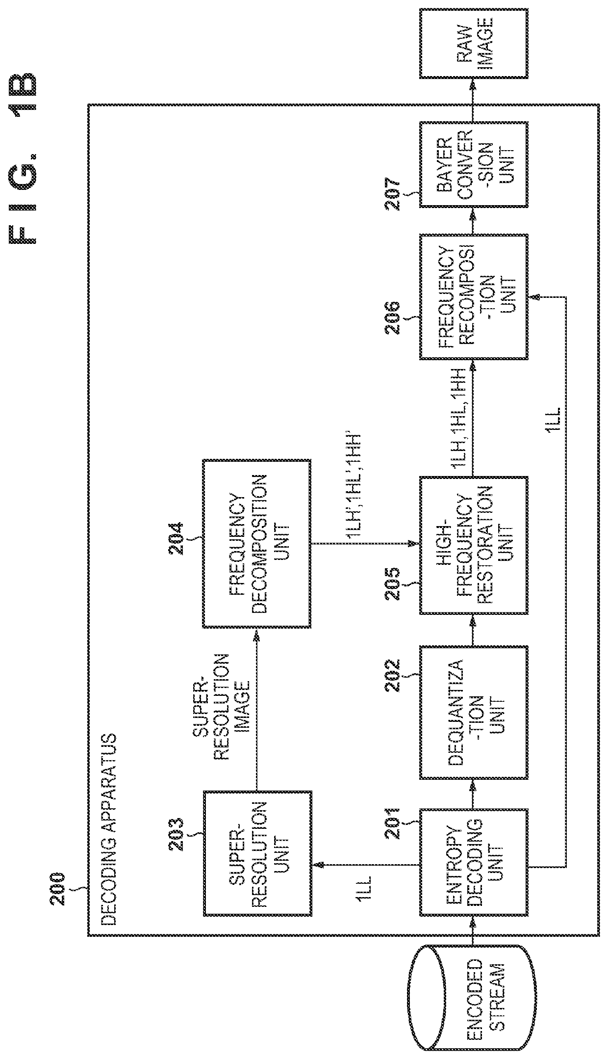
[0031]FIG. 1A is a block diagram showing an exemplary function configuration of an encoding apparatus 100 according to an embodiment of the present disclosure. The encoding apparatus 100 includes a plane conversion unit 101, a frequency decomposition unit 102, a super-resolution unit 103, a high-frequency difference computation unit 104, a quantization unit 105, an entropy encoding unit 106, and a quantization parameter setting unit 107. These units (functional blocks) can be realized by a dedicated hardware circuit such as an ASIC, as a result of general-purpose processor such as a DSP or a CPU loading a program stored in a non-volatile memory to a system memory and executing the program, or by a combination thereof. For convenience, a description will be given below assuming that each functional block autonomously operates in cooperation with other functional blocks.

[0032]Here, assume that RAW image data (first image data) to be encoded is data read out from image sensor provided...

second embodiment

[0130]Next, a second embodiment of the present disclosure will be described with reference to FIG. 15A. In FIG. 15A, the same reference numerals are assigned to functional blocks that are similar to those of the encoding apparatus 100 described in the first embodiment. An encoding apparatus 1800 according to this embodiment has a functional configuration similar to that of the encoding apparatus 100 described in the first embodiment, except that a dequantization unit 1801 is included. Therefore, differences from the first embodiment will be described below mainly.

[0131]In the first embodiment, a configuration is adopted in which subband data of a low-frequency component 1LL is not quantized, but, in this embodiment, subband data of 1LL is also quantized. The quantized subband data of 1LL is then subjected to dequantization performed by the dequantization unit 1801, and is supplied to the super-resolution unit 103.

[0132]Therefore, according to this embodiment, the frequency decomposi...


PUM


Abstract

An encoding apparatus generates low-frequency component subband data and high-frequency component subband data from image data; generates, from low-frequency component subband data generated from first image data, second image data that has a same resolution as that of the first image data. The apparatus obtains a difference between high-frequency component subband data generated from the first image data and high-frequency component subband data generated from the second image data; and encodes the low-frequency component subband data of the first image data and the difference in order to generate encoded data.

Description

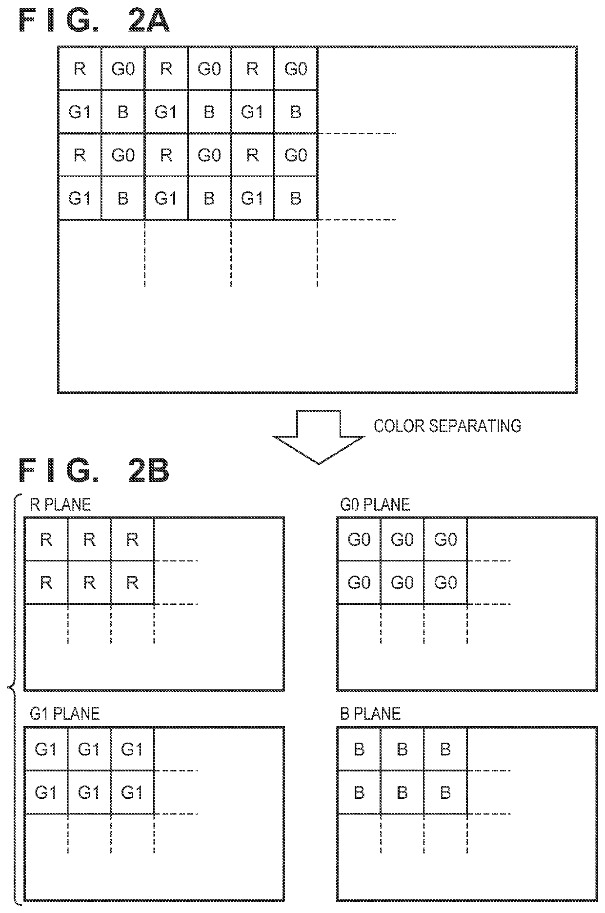
BACKGROUND OF THE INVENTIONField of the Invention[0001]The present disclosure relates to an encoding apparatus and encoding method, and a decoding apparatus and decoding method.Description of the Related Art[0002]A color filter array (also referred to as “CFA”) is provided in a single-plate color image sensor that is widely used in digital cameras. Filters of a plurality of predetermined colors are regularly arranged in the color filter array. There are various color combinations and arrangement methods for the color filter array, but the primary-color Bayer filter shown in FIG. 2 is representative.[0003]In the primary-color Bayer filter, unit filters of R (red), G0 (green), G1 (green), and B (blue) are cyclically arranged in units of 2*2. One unit filter is provided for each pixel of an image sensor, and thus pixel data that constitutes image data obtained in one instance of shooting includes only information of one color component of RGB. Image data in this state is called RAW ima...

Claims


Application Information

Patent Timeline
IPC IPC(8): H04N19/169H04N19/124H04N19/186H04N19/63
CPCH04N19/1883H04N19/63H04N19/186H04N19/124H04N19/147
Inventor SAKAMOTO, DAISUKE
Owner CANON KK
Learn More