
Foldable equipment rack

a technology of equipment racks and racks, applied in the field of equipment racks, can solve the problems of reducing fuel efficiency and wind noise, and reducing the useful life of equipment racks, and achieve the effect of overcompensating friction resistan

Inactive Publication Date: 2021-05-06
KUAT INNOVATIONS
View PDF0 Cites 4 Cited by
  • Summary
  • Abstract
  • Description
  • Claims
  • Application Information

AI Technical Summary

Benefits of technology

The patent describes an equipment rack that can be easily moved and locked in place. The rack has a hinge that can pivot the rack assembly from a stowed position to an operational position, and a positional latch mechanism that can hold the rack assembly in either position. The positional latch mechanism is attached to the rack assembly and the hinge, and can be actuated to release the rack assembly from the stored position. The equipment rack also includes a socket that can receive a shuttle member, which is a part of the positional latch mechanism. This allows for easy locking and unlocking of the rack assembly. The design of the rack and hinge is flexible, allowing for different ways to lock the rack in place.

Problems solved by technology

Since these racks are externally mounted on the vehicle they contribute to wind drag that reduces fuel efficiency as well as wind noise that may be a nuisance to occupants of the vehicle.
The wind pressure may also cause additional wear and tear on the equipment racks when they are not in use, thus reducing the useful life of the equipment rack.
The alternative of removing the equipment rack from the vehicle between each use is unacceptable because the equipment racks are typically attached to the vehicle in a manner that may require tools or an unacceptable amount of additional time to remove the equipment racks, and to reinstall the equipment racks.

Method used


Image

  • Foldable equipment rack
  • Foldable equipment rack
  • Foldable equipment rack

Examples


Embodiment Construction

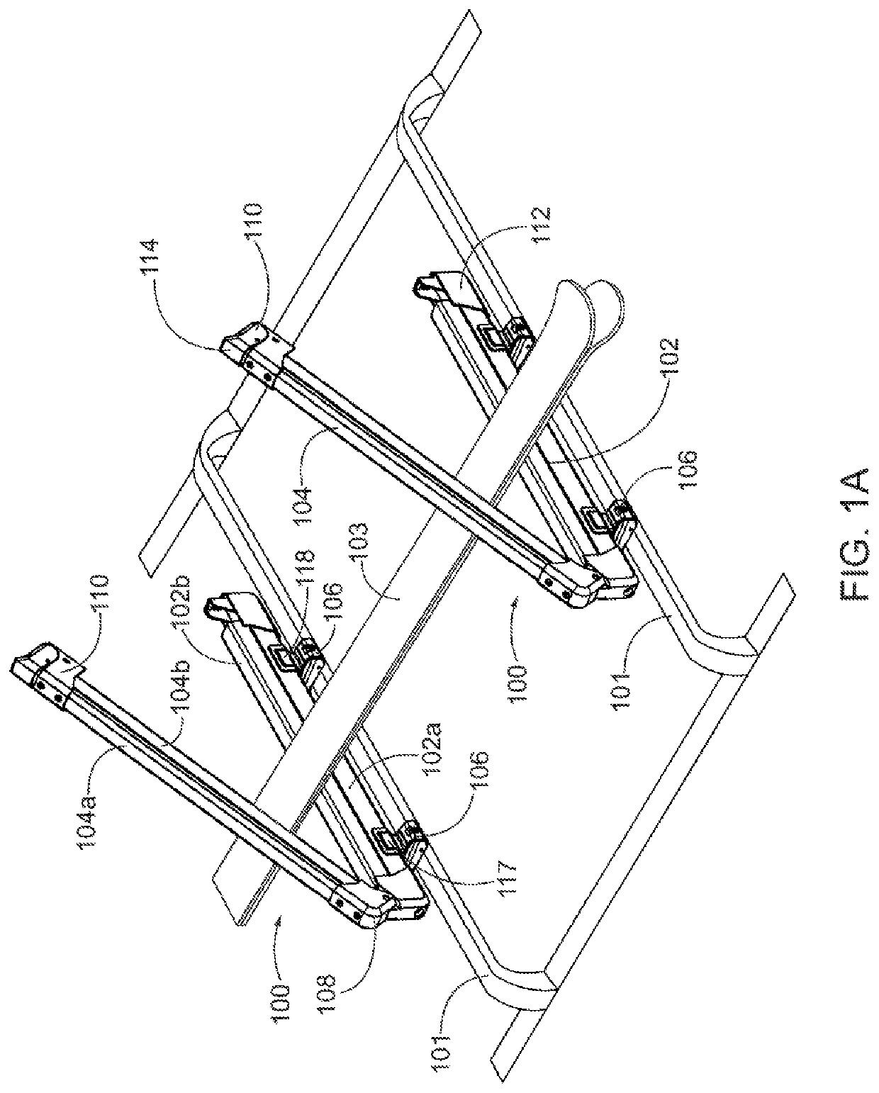
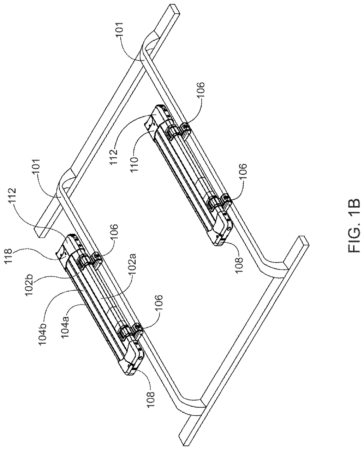
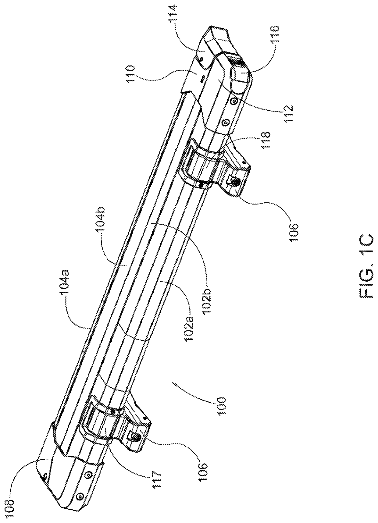
[0042]The inventive rack disclosed herein is capable of pivoting from an operational position to a stowed position, and vice versa. The exemplary rack is a type that may be used to securely carry skis or a snowboard on the exterior of a vehicle. The inventive rack may also be used for other types of equipment such as racks for kayaks, surfboards, and other similar equipment. In some embodiments a positional latch mechanism is used to secure the device in a desired position, such as the operational position, a stowed position, or any other relative positions, and to prevent unintentional movement of the rack assembly 100 from that desired position. The positional latch mechanism is provided with a means for actuating, releasing, disengaging, or otherwise freeing the latch mechanism so that the rack assembly 100 may be repositioned from one desired position to another. The positional latch mechanism may also be provided with a mechanism for reengaging the positional latch mechanism on...


PUM


Abstract

The equipment rack for attaching equipment to the roof of a vehicle includes a rack assembly that may be folded from a stowed position to an operational position. The rack assembly is attached to the vehicle by a hinge and a positional latch mechanism to selectively retain the rack assembly in the stowed position or the operational position. The user of the rack may selectively pivot the rack assembly from one position to another. The pivotal latch mechanism may retain the rack assembly in one, two, or more desired positions. Some versions of the latch mechanism utilize a shuttle member in one element that engages a socket in the other element. Other versions of the latch mechanism utilize surfaces on the rack assembly and the hinge interact to retain the rack assembly at desired positions.

Description

CROSS-REFERENCE TO RELATED APPLICATIONS[0001]None.BACKGROUNDField of the Invention[0002]This disclosure is in the field of equipment racks for carrying equipment on vehicles. More specifically, this disclosure is in the field of externally mounted equipment racks for use on a vehicle to temporarily carry equipment such as skis, snowboards, kayaks, or other types of equipment.Description of the Related Art[0003]Various designs for externally mounted equipment racks have been used to carry skis, snowboards, and other similar types of equipment on a vehicle to transport the equipment from place to place. Such racks are typically externally mounted on the vehicle in a semi-permanent manner, such that they may be removed when not in use, but are often left on the vehicle between uses of the rack to carry equipment. Since these racks are externally mounted on the vehicle they contribute to wind drag that reduces fuel efficiency as well as wind noise that may be a nuisance to occupants of ...

Claims


Application Information

Patent Timeline
Patent Type & Authority Applications(United States)
IPC IPC(8): B60R9/048B60R9/058
CPCB60R9/048B60R9/12B60R9/058
Inventor SCHWARTZ, JOSHKUSCHMEADER, LUKEBOWLES, JORDAN
Owner KUAT INNOVATIONS
Learn More