
Method of making a piezoelectric MEMS diaphragm microphone

a piezoelectric and diaphragm technology, applied in the direction of diaphragm construction, microphone structural association, loudspeaker, etc., can solve the problems of bias voltage, poor low-frequency roll-off control of cantilever mems structure, high power consumption of conventional capacitive mems microphones, etc., to achieve better low-frequency roll-off control, reduce overall residual stress in the diaphragm, and improve the effect of sensitivity

Active Publication Date: 2021-04-22
SKYWORKS SOLUTIONS INC
View PDF0 Cites 1 Cited by
  • Summary
  • Abstract
  • Description
  • Claims
  • Application Information

AI Technical Summary

Benefits of technology

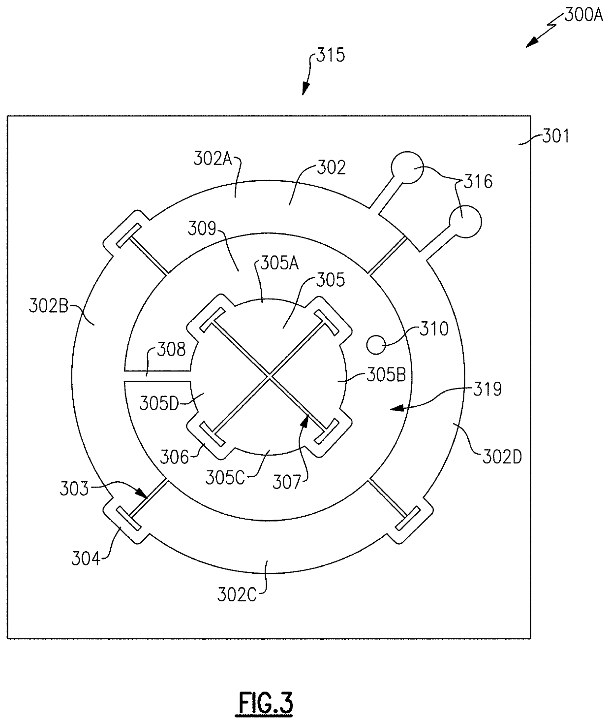
[0007]In accordance with one aspect of the disclosure, a multi-piezoelectric-layer MEMS diaphragm microphone is provided that substantially cancels the overall residual stress in the diaphragm. The multi-piezoelectric-layer MEMS diaphragm microphone advantageously provides higher sensitivity (e.g., how much voltage is measured when diaphragm is provided to sound pressure) and better lower frequency roll-off as compared to the MEMS cantilever structure. The multi-piezoelectric-layer MEMS diaphragm microphone can optionally include two or more piezoelectric films with predefined residual stress (e.g., during film deposition) that substantially balance (e.g., cancel) out residual stress in the diaphragm structure.

Problems solved by technology

Conventional capacitive MEMS microphones suffer from high power consumption (e.g., large bias voltage) and reliability, for example when used in a harsh environment (e.g., when exposed to dust and / or water).
The cantilever MEMS structure suffers from poor low-frequency roll-off control as the gap between cantilevers varies when cantilevers deflect due to residual stress.
Additionally, the cantilever MEMS structure with gap control mechanism can have a complex structure that results in higher manufacturing costs and poor reliability performance.
The diaphragm MEMS structure provides better low-frequency roll-off control and higher sensitivity than the cantilever MEMS structure, but suffers from sensitivity variation as residual stress causes large tensile or compression stresses within the diaphragm (e.g., a small residual stress results in a large sensitivity degradation for diaphragm type piezoelectric MEMS microphone).

Method used


Image

  • Method of making a piezoelectric MEMS diaphragm microphone
  • Method of making a piezoelectric MEMS diaphragm microphone
  • Method of making a piezoelectric MEMS diaphragm microphone

Examples


Embodiment Construction

[0074]The following detailed description of certain embodiments presents various descriptions of specific embodiments. However, the innovations described herein can be embodied in a multitude of different ways, for example, as defined and covered by the claims. In this description, reference is made to the drawings were like reference numerals can indicate identical or functionally similar elements. It will be understood that elements illustrated in the figures are not necessarily drawn to scale. Moreover, it will be understood that certain embodiments can include more elements than illustrated in a drawing and / or a subset of the elements illustrated in a drawing. Further, some embodiments can incorporate any suitable combination of features from two or more drawings.

[0075]The International Telecommunication Union (ITU) is a specialized agency of the United Nations (UN) responsible for global issues concerning information and communication technologies, including the shared global u...


PUM


Abstract

A piezoelectric microelectromechanical systems diaphragm microphone can be mounted on a printed circuit board. The microphone can include a substrate with an opening between a bottom end of the substrate and a top end of the substrate. The microphone can have two or more piezoelectric film layers disposed over the top end of the substrate and defining a diaphragm structure. Each of the two or more piezoelectric film layers can have a predefined residual stress that substantially cancel each other out so that the diaphragm structure is substantially flat with substantially zero residual stress. The microphone can include one or more electrodes disposed over the diaphragm structure. The diaphragm structure is configured to deflect when the diaphragm is subjected to sound pressure via the opening in the substrate.

Description

INCORPORATION BY REFERENCE TO ANY PRIORITY APPLICATIONS[0001]Any and all applications for which a foreign or domestic priority claim is identified in the Application Data Sheet as filed with the present application, including U.S. patent application Ser. No. 16 / 890,858, filed Jun. 2, 2020 and titled “PIEZOELECTRIC MEMS DIAPHRAGM MICROPHONE”, U.S. Provisional Patent Application No. 62 / 857,675, filed Jun. 5, 2019 and titled “PIEZOELECTRIC MEMS DIAPHRAGM MICROPHONE,” and U.S. Provisional Patent Application No. 62 / 857,701, filed Jun. 5, 2019 and titled “METHOD OF MAKING A PIEZOELECTRIC MEMS DIAPHRAGM MICROPHONE,” are hereby incorporated by reference under 37 CFR 1.57.BACKGROUNDField[0002]The present disclosure is directed to a piezoelectric microelectromechanical systems (MEMS) microphone, and in particular to a multi-layer piezoelectric MEMS diaphragm microphone.Description of the Related Art[0003]A MEMS microphone is a micro-machined electromechanical device used to convert sound pres...

Claims


Application Information

Patent Timeline
Patent Type & Authority Applications(United States)
IPC IPC(8): H04R17/02H04R19/04B81B3/00H04R7/10H04R1/04
CPCH04R17/02H04R19/04B81B3/0072H04R7/10H04R1/04H04R2499/11B81B2203/0127H04R2201/003B81B2201/0257B81B2203/019H04R2420/07B81B2203/04H04R2430/20B81C2201/0167
Inventor HUI, YUSHIN, KWANG JAE
Owner SKYWORKS SOLUTIONS INC
Learn More