
Wireless communication apparatus and display method for use in wireless communication apparatus

a wireless communication and display method technology, applied in the direction of transmission monitoring, multi-channel direction-finding system using radio waves, receiveer monitoring, etc., can solve the problems of weak radio waves, large propagation loss, and difficulty in extending the wireless reach range, so as to improve the communication quality and affect the communication quality

Active Publication Date: 2021-04-08
PANASONIC INTELLECTUAL PROPERTY CORP OF AMERICA
View PDF0 Cites 0 Cited by
  • Summary
  • Abstract
  • Description
  • Claims
  • Application Information

AI Technical Summary

Benefits of technology

[0006]In a wireless network using a millimeter wave band, a terminal performs beamforming training in order to control the directivity for a base station apparatus to be connected. However, the rectilinearity of radio waves in the millimeter wave band is strong and the radio waves are weak against obstacles. Thus, when the radiating angle range of the radio waves is narrow and if at least one of the posture and the orientation of the terminal is changed, the communication coverage area changes. Accordingly, at least one of the posture and the orientation of the terminal affects the communication quality. However, the user does not know which direction the terminal is facing will improve the communication quality.
[0007]One non-limiting and exemplary embodiment provides a wireless communication apparatus that performs communication using a millimeter wave band and that enables a user to identify at least one of the posture and the orientation of the apparatus that improves the communication quality of the apparatus and a display method for use in the wireless communication apparatus.
[0009]According to the aspect of the present disclosure, a user is enabled to identify the posture / orientation of an apparatus that improves the communication quality of the apparatus.

Problems solved by technology

Accordingly, the propagation loss is larger than that in the microwave band and, therefore, it is difficult to extend the wireless reach range.
However, the rectilinearity of radio waves in the millimeter wave band is strong and the radio waves are weak against obstacles.
However, the user does not know which direction the terminal is facing will improve the communication quality.

Method used


Image

  • Wireless communication apparatus and display method for use in wireless communication apparatus
  • Wireless communication apparatus and display method for use in wireless communication apparatus
  • Wireless communication apparatus and display method for use in wireless communication apparatus

Examples


first embodiment

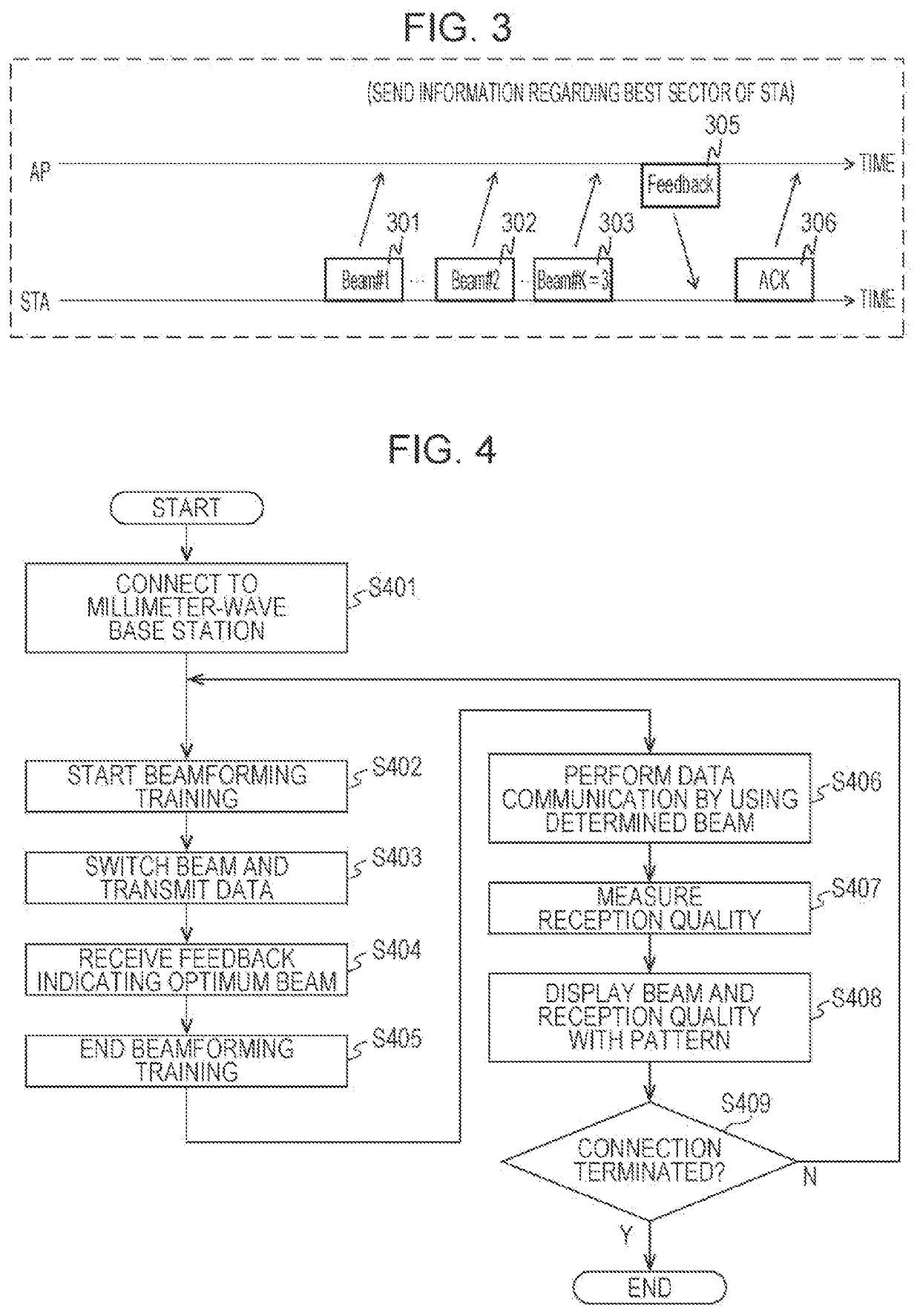
[0045]An example of the operation performed by the millimeter-wave terminal according to a first embodiment is described below with reference to FIG. 4.

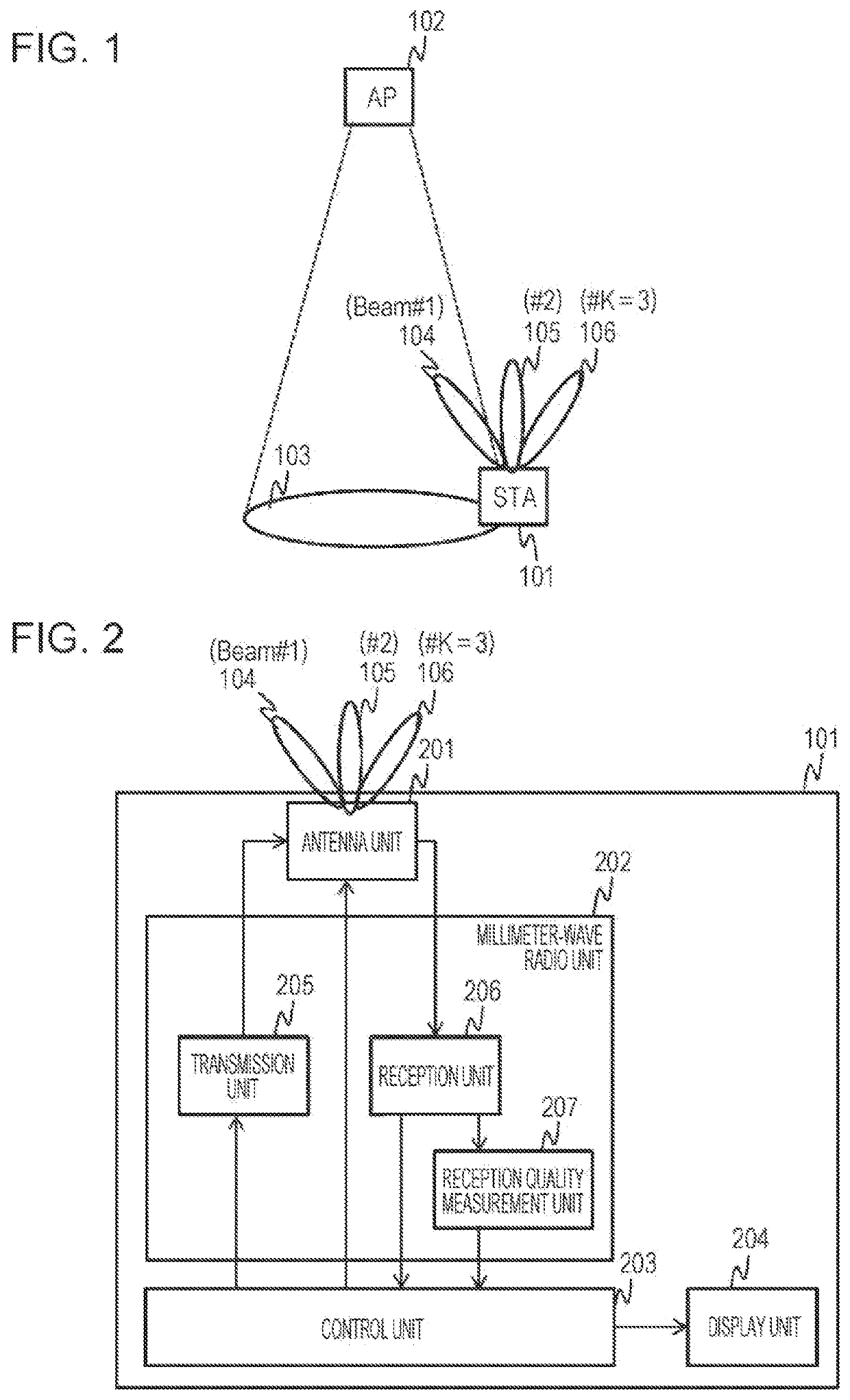
[0046]A terminal (an STA) according to the present embodiment has a single antenna and forms a beam by the single antenna.

[0047]FIG. 4 is a flowchart illustrating the control performed by the control unit 203 of the STA 101 before a display operation is performed according to the present embodiment.

[0048]In step S401, the STA 101 starts establishing connection with the AP 102. For example, the STA 101 detects that it has entered the communication coverage area 103 by detecting a beacon frame periodically transmitted by the AP 102. Thereafter, the STA 101 sends a connection request to the AP 102.

[0049]After establishing connection with the AP 102, the STA 101 starts beamforming training (step S402). As described above, each time the STA 101 switches between beams, the STA 101 transmits a training frame (step S403), receives a feedback...

second embodiment

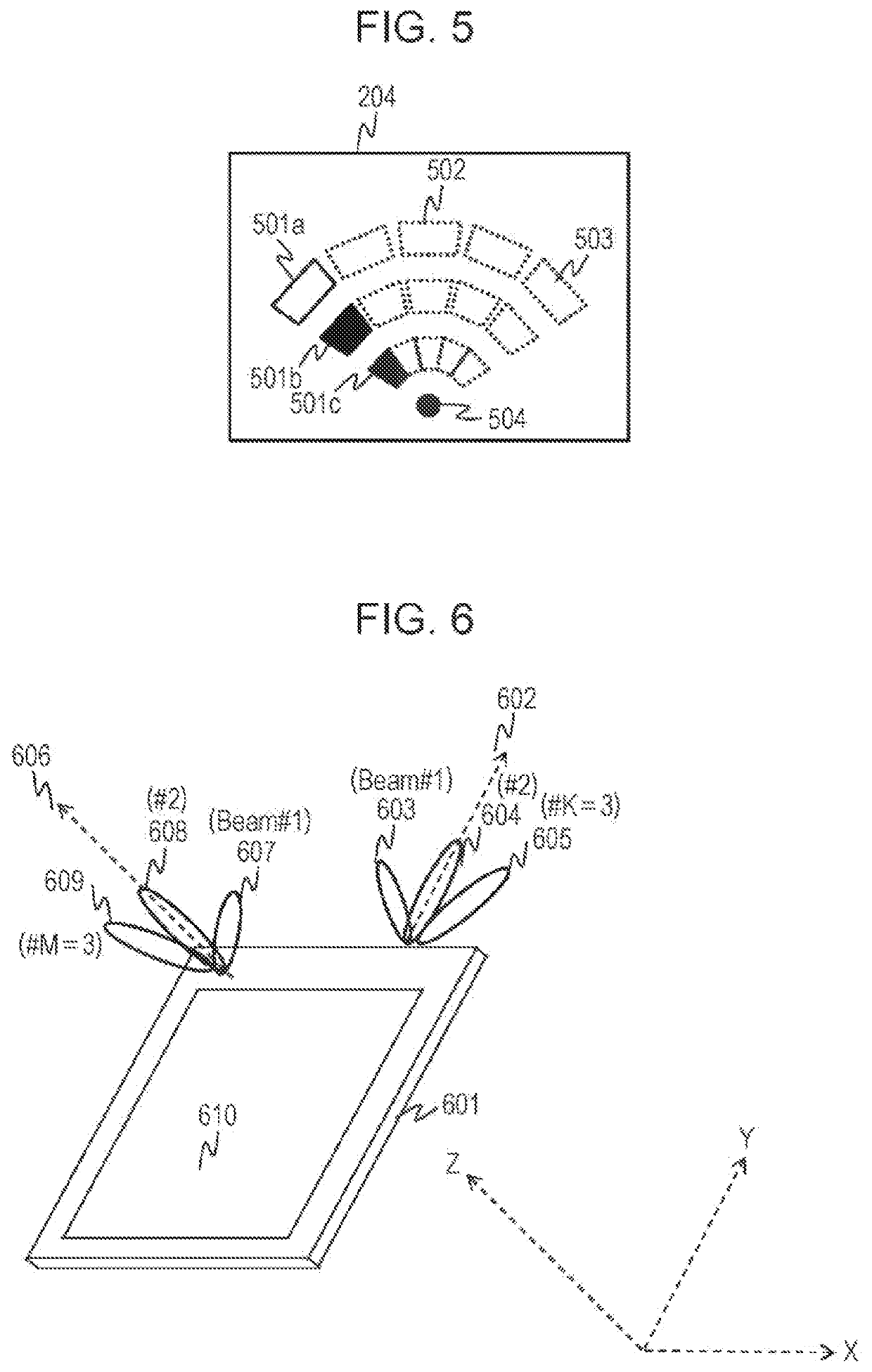
[0057]According to the above-described first embodiment, the description has been given with reference to the display in the case where the terminal (the STA) has a single antenna, and the beam is formed by the single antenna. According to the present embodiment, a display scheme in the case where a terminal has a plurality of antennas with different beamforming directions is described.

[0058]More specifically, in the terminal, a plurality of antennas are mounted at different angles. Among the plurality of antennas, an antenna (an antenna unit) 1 is an antenna that radiates radio waves in the forward direction of the user when the user views the display unit and operates the terminal. An antenna (an antenna unit) 2 is an antenna that radiates radio waves in the backward direction of the user when the user views the display unit and operates the terminal.

[0059]FIG. 6 illustrates an example of a terminal having a plurality of antennas. In FIG. 6, a terminal (a casing) 601, a radiation ...

third embodiment

[0089]According to the present embodiment, a display scheme is described in the case where communication using the microwave band can be performed in addition to communication using the millimeter wave band described above in the first and second embodiments.

[0090]FIG. 11 illustrates an example of a heterogeneous network system formed by combining microwave communication with millimeter wave communication. In FIG. 11, a terminal 1101 is a multiband terminal that can perform communication by using both millimeter waves and microwaves. A millimeter-wave base station apparatus 1102, a communication coverage area 1103 of the millimeter-wave base station apparatus 1102, beams 1104, 1105, and 1106 formed by millimeter wave antennas of the multiband terminal 1101, a microwave base station apparatus 1107, and a communication coverage area 1108 of the microwave base station apparatus 1107 are illustrated in FIG. 11. The microwave base station apparatus 1107 is a wireless LAN that uses the 2....


PUM


Abstract

A wireless communication apparatus includes a first antenna circuit that forms a beam selected from among a plurality of first beams through a beamforming process performed for communication using a millimeter wave band and a monitor that displays a first pattern indicating a radiation direction of the selected beam.

Description

BACKGROUND1. Technical Field[0001]The present disclosure relates to a wireless communication apparatus and a display method for use in the wireless communication apparatus.2. Description of the Related Art[0002]In recent years, in order to ensure a bandwidth of at least 1 GHz in response to the rapid increase in traffic demand, introduction of a small base station apparatus that performs communication using a millimeter wave band has been studied. For example, a communication system in which a plurality of small base station apparatuses are provided within a communication area of a base station apparatus that performs communication using a microwave band (also referred to as a heterogeneous network) is one of the alternatives of the plan.[0003]Such a small base station apparatus uses a millimeter wave band. Accordingly, the propagation loss is larger than that in the microwave band and, therefore, it is difficult to extend the wireless reach range.[0004]As one of techniques to reduc...

Claims


Application Information

Patent Timeline
Patent Type & Authority Applications(United States)
IPC IPC(8): H04B7/06H04B17/23G01S3/02G01S3/74H04B17/318H04B17/20H04B7/0417H04W16/28H04W72/04
CPCH04B7/0617H04B17/23G01S3/02G01S3/74H04B17/318H04B7/10H04B7/0417H04B7/0695H04W16/28H04W72/0446H04B17/20H04W72/046H04B7/0408H04W88/08
Inventor SHIRAKATA, NAGANORISHIMIZU, MASAYUKITAKINAMI, KOJI
Owner PANASONIC INTELLECTUAL PROPERTY CORP OF AMERICA
Learn More