
Multiband antenna

a multi-band antenna and antenna technology, applied in the field of multi-band antennas, can solve the problems of large size, difficult to precisely install, complicated structure of multi-band antennas,

Inactive Publication Date: 2011-08-30
CHI MEI COMM SYST INC
View PDF6 Cites 7 Cited by
  • Summary
  • Abstract
  • Description
  • Claims
  • Application Information

AI Technical Summary

Benefits of technology

The present patent is about a multiband antenna for wireless cards that can improve communication quality while keeping the antenna small in size. The technical effect of the patent is to provide a multiband antenna that can be installed in wireless cards with precision, while maintaining the size of the card.

Problems solved by technology

However, most conventional multiband antennas have complicated structures and are large in size, while many wireless cards are small with insufficient space to install the multiband antennas.
Even if some miniaturized multiband antennas can be installed in wireless cards, they are difficult to be installed precisely.
Thus, communication quality of the wireless card may be affected.

Method used


Image

  • Multiband antenna
  • Multiband antenna
  • Multiband antenna

Examples


Embodiment Construction

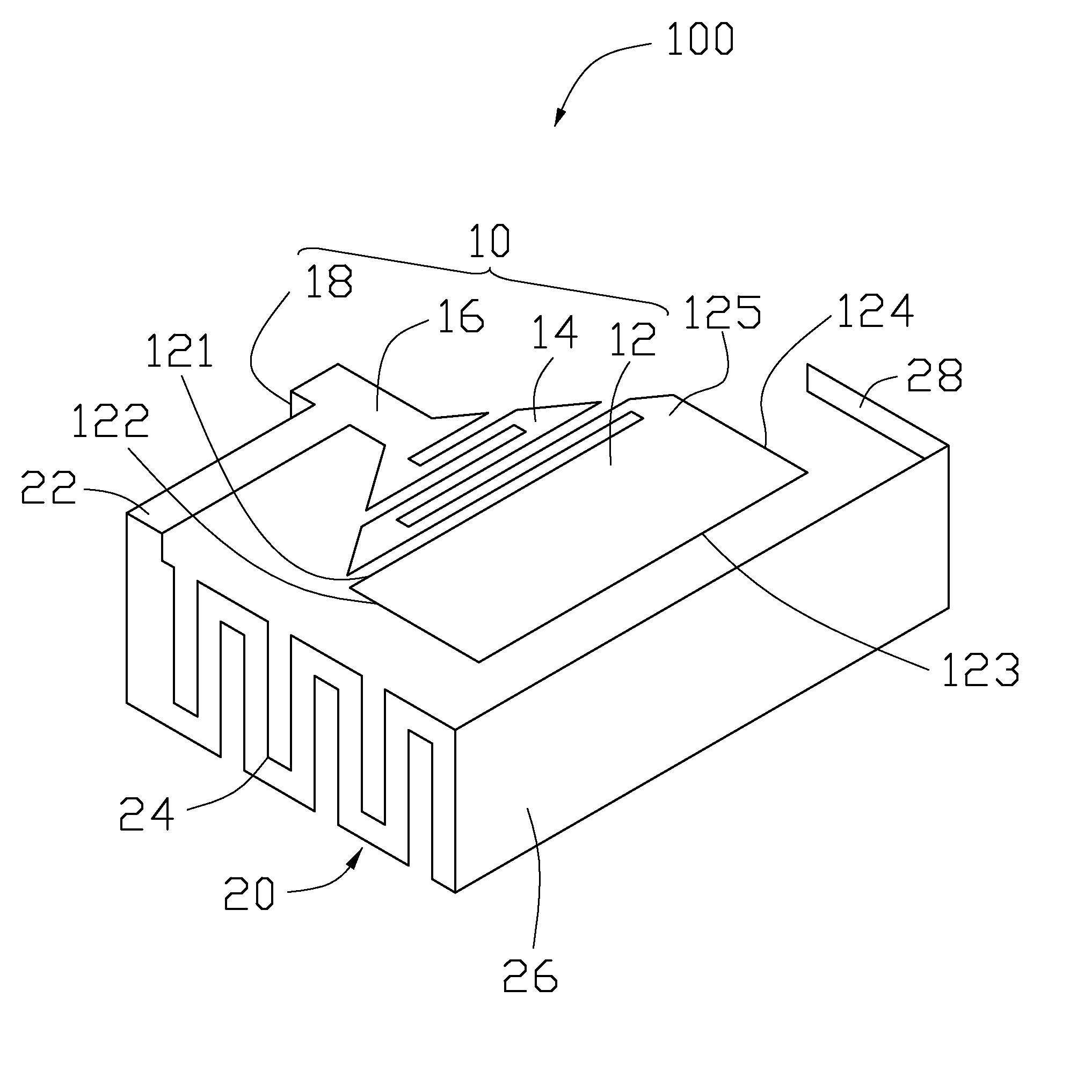
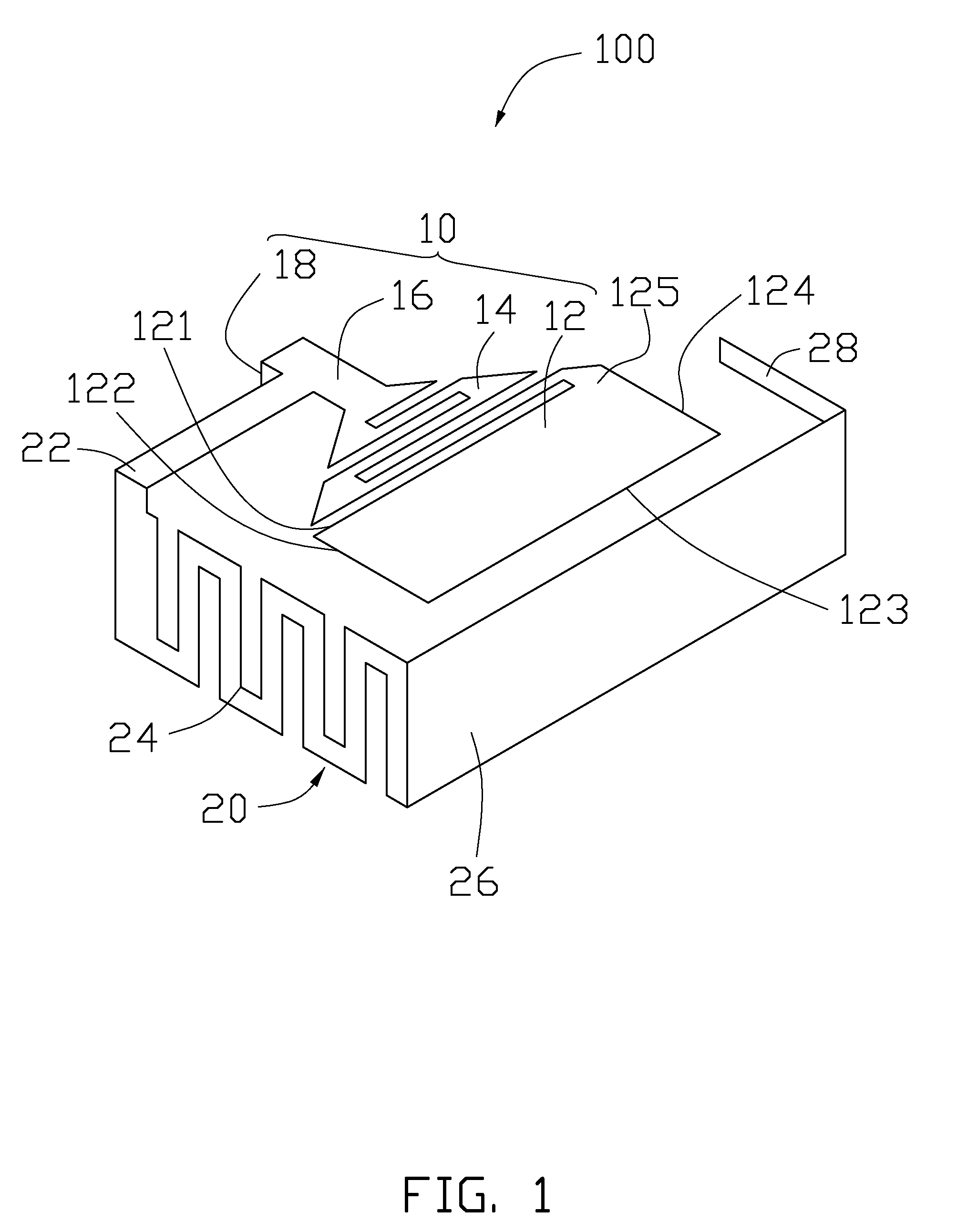
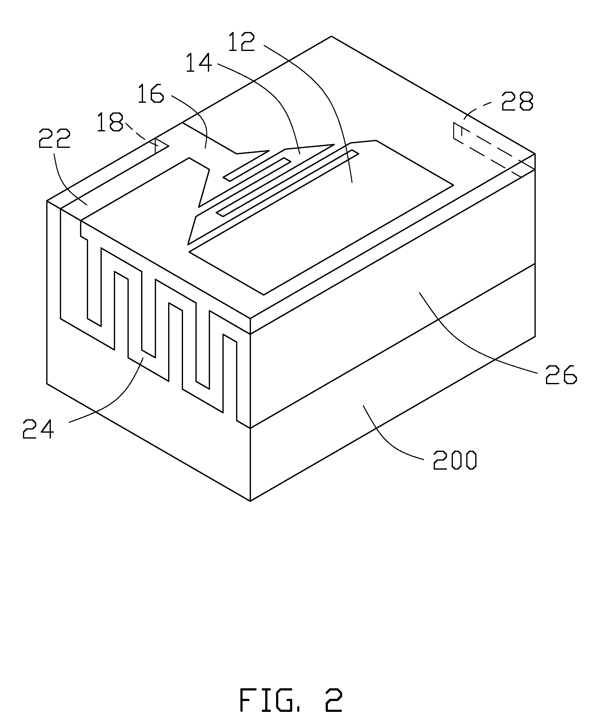
[0011]FIG. 1 schematically shows a multiband antenna 100 according to an exemplary embodiment, for use in wireless cards. The multiband antenna 100 is made of conductive materials, such as metal. The multiband antenna 100 includes a first antenna unit 10 and a second antenna unit 20 connected to the first antenna unit 10. The first antenna unit 10 is used to receive or send wireless signals having higher frequencies, and the second antenna unit 20 is used to receive or send wireless signals having lower frequencies.

[0012]The first antenna unit 10 includes a first main portion 12, a first resonating portion 14, a first connecting portion 16 and a first feed portion 18. The first main portion 12 is a rectangular sheet, which includes two parallel longer sides 121, 123 and two parallel shorter sides 122, 124 perpendicular to the sides 121, 123. The side 121 intersects the side 124 at a corner 125.

[0013]The first resonating portion 14 is a zigzag sheet connected to the first main portio...


PUM


Abstract

A multiband antenna includes a first antenna unit for receiving / sending wireless signals having higher frequencies and a second antenna unit for receiving / sending wireless signals having lower frequencies than those frequencies received / sent by the first antenna unit. The first antenna unit includes a first main portion, a first resonating portion and a first connecting portion connected in order and positioned in a same plane. The second antenna unit includes a second connecting portion, a second resonating portion and a second main portion connected in order. The second connecting portion is coplanar with the first connecting portion, the second resonating portion is perpendicular to the second connecting portion, and the second main portion is perpendicular to both the first connecting portion and the second connecting portion.

Description

BACKGROUND[0001]1. Technical Field[0002]The present disclosure relates to multiband antennas, and particularly to a multiband antenna for wireless cards.[0003]2. Description of Related Art[0004]Wireless cards are widely used in portable electronic devices such as mobile phones, personal digital assistants (PDA) and laptop computers. Antennas are used in such wireless cards to receive / send wireless signals. Generally, an antenna of a wireless card may receive / send wireless signals of different frequencies (e.g., DCS1800, PCS1900, UMTS2100, etc.), requiring that the antenna be a multiband antenna.[0005]However, most conventional multiband antennas have complicated structures and are large in size, while many wireless cards are small with insufficient space to install the multiband antennas. Even if some miniaturized multiband antennas can be installed in wireless cards, they are difficult to be installed precisely. Thus, communication quality of the wireless card may be affected.[0006...

Claims


Application Information

Patent Timeline
Patent Type & Authority Patents(United States)
IPC IPC(8): H01Q1/24H01Q21/30H01Q5/10H01Q5/371
CPCH01Q1/38H01Q5/371H01Q21/30
Inventor HUNG, CHUNG-YU
Owner CHI MEI COMM SYST INC
Learn More