Redundant Automation System, Method for Creating the Automation System, Computer Program and Computer Readable Medium

a technology of automation system and automation system, applied in the direction of programme control, total factory control, instruments, etc., can solve the problems of inability to meet the requirements of automation technology, stop the automation installation, and the availability of such conventional systems considered inadequate for applications in automation technology

Active Publication Date: 2021-04-08
SIEMENS AG
View PDF0 Cites 0 Cited by
  • Summary
  • Abstract
  • Description
  • Claims
  • Application Information

AI Technical Summary

Benefits of technology

[0007]This and other objects and advantages are achieved in accordance with the invention by a redundant automation system comprising at least one automation installation to be controlled, which is installed at an installation location and two control applications, which are communicatively coupled to one another via a synchronization path, configured to control the automation installation, form part of a cloud-computing structure of which the computing resources are provided at different locations and which are communicatively connected to the automation installation via the internet or via a comparable computer network, and which has a plurality of communication hubs and communication paths connecting these to one another, where one of the control applications operates as the master and the other control application operates as a reserve, such that in the event that the control application operating as the master fails, the control application operates as a reserve takes over and functions as the master and where the locations of the computing resources for the control applications are selected such that the control applications are connected to the automation installation via two different communication paths that preferably have no or a minimal number of common communication hubs. Therefore, in accordance with the invention, the control applications are outsourced to a cloud. Herein, to improve the mean time to failure (MTTF), the control applications are communicatively connected to the automation installation or to the peripheral units thereof via separate communication paths of the internet or the comparable computer network. Herein, it is ensured that the communication paths have no or, if this is not possible due the installation location and / or locations of the computing resources for the control applications in relation to the topology of the internet or the comparable computer network, a minimal number of common communication hubs. This is advantageous because, if the communication path between the control application working as the master and the automation installation were to fail, reliable function of the communication path between the control application operating as the reserve and the automation installation is ensured and the control application operating as the reserve can take over and function as the master. This results in an improvement of the MTTF of the control applications to a value suitable for automation technology.

Problems solved by technology

Therefore, the users of cloud-based services must assume their applications will be unavailable for a few minutes each month.
In the case of a control application, this unavoidably results in a stoppage of the automation installation, which will probably be unacceptable to the operator of the installation.
However, the availability of such conventional system considered inadequate for applications in automation technology because the status of the control applications, and hence of the automation process, must be maintained in the event of a failure.
This can only be achieved by using “hot stand-by” systems.

Method used


Image

  • Redundant Automation System, Method for Creating the Automation System, Computer Program and Computer Readable Medium
  • Redundant Automation System, Method for Creating the Automation System, Computer Program and Computer Readable Medium
  • Redundant Automation System, Method for Creating the Automation System, Computer Program and Computer Readable Medium

Examples


Embodiment Construction

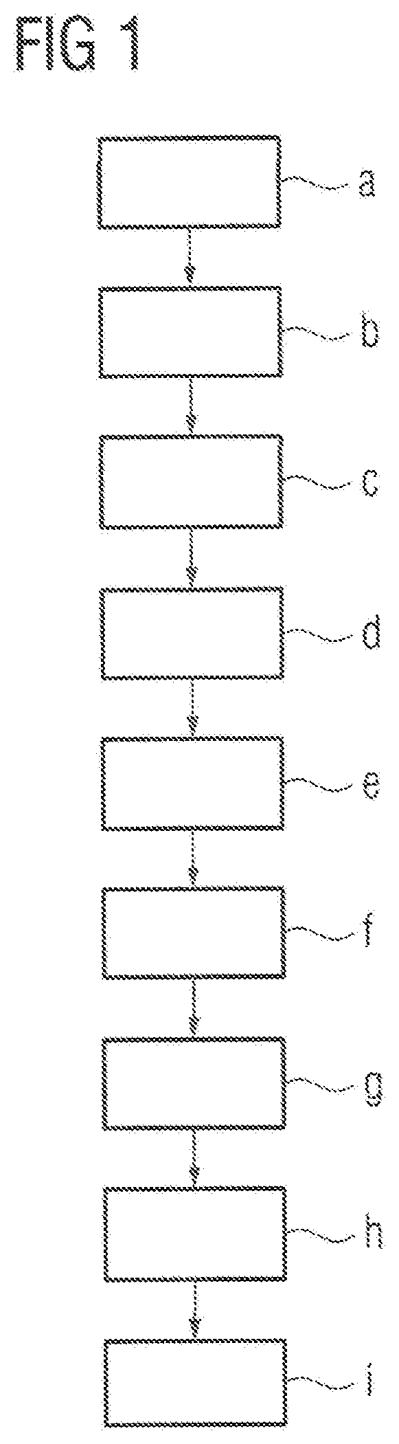
[0029]FIG. 1 is a schematic depiction of method steps a) to i) of a method in accordance with one embodiment of the present invention, which is used to create a redundant automation system 1 for an automation installation to be controlled 2.

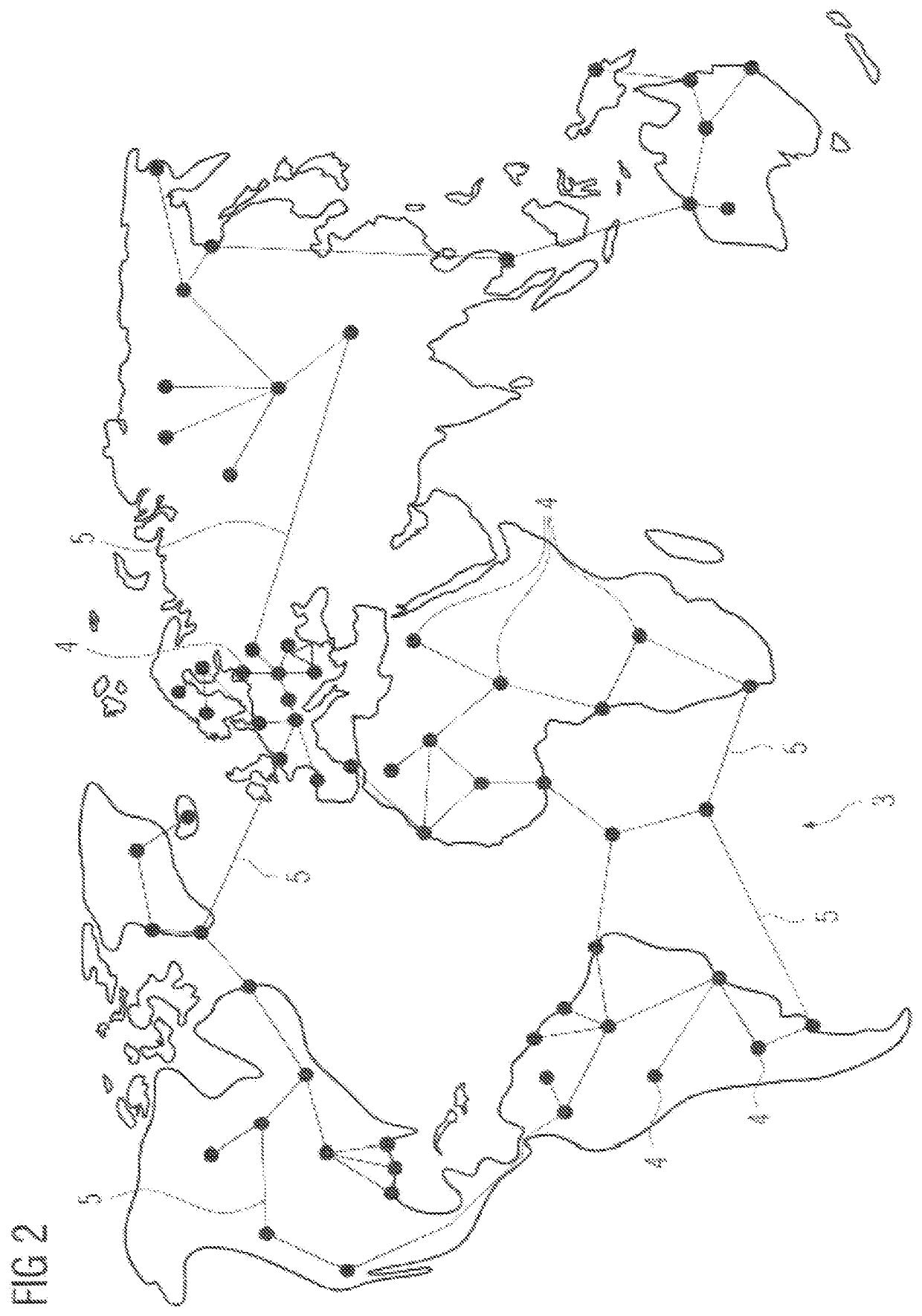
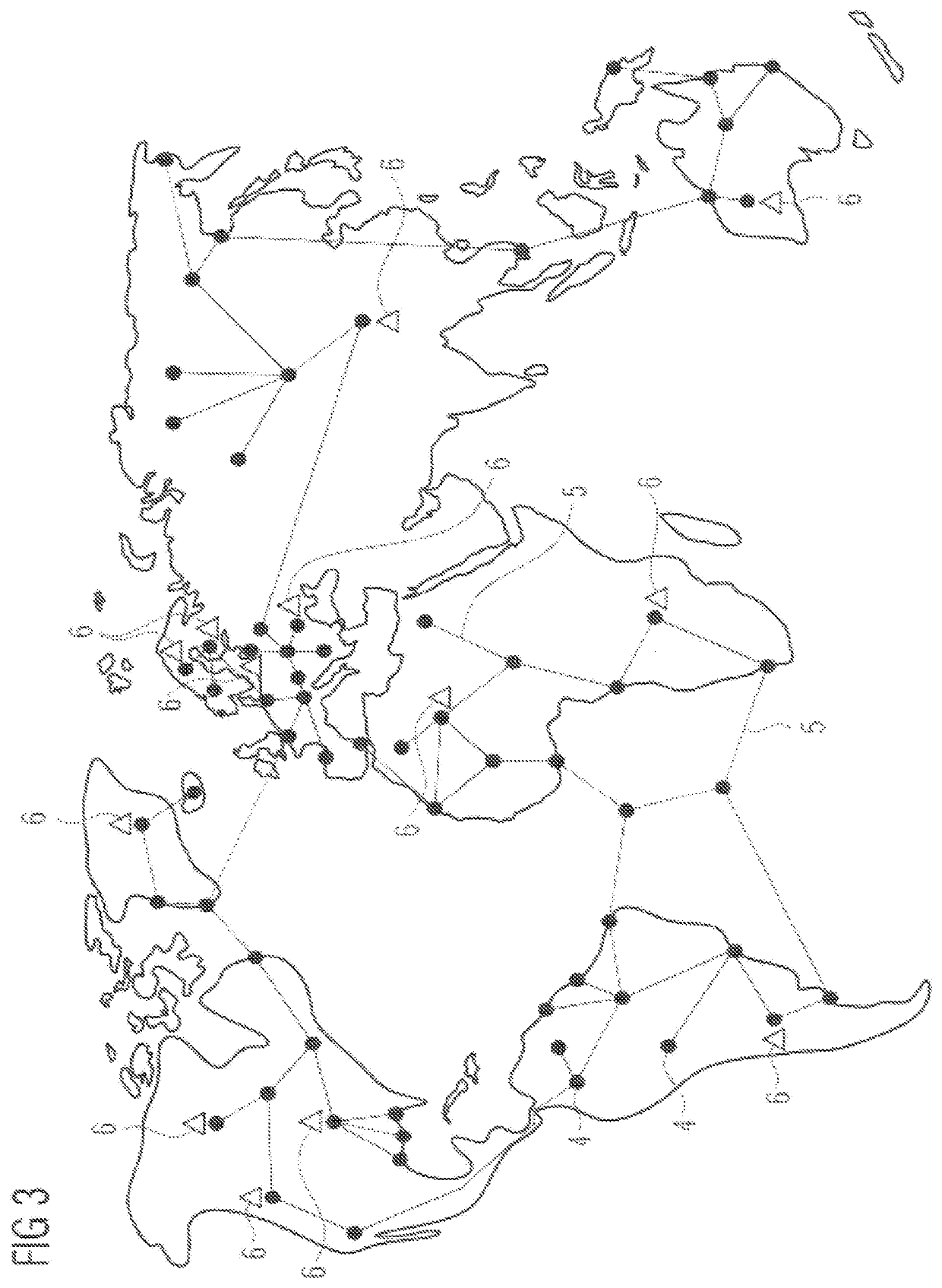
[0030]In a first step a), information on the topology of a computer network 3 is provided. In the present case, the computer network 3 is the Internet. However, alternatively, the computer network 3 can also be a comparable computer network, such as a company intranet communicatively connecting a plurality of company locations to one another. The information provided in step a) is at least information on the structure or partial structure of the computer network 3, which is formed by communication hubs 4 and communication paths 5 interconnecting these to one another. The communication paths 5 can be wired and / or radio-based transmission links. Here, the information was obtained based on static information, such as maps showing currently existing ...


PUM


Abstract

A method for creating a redundant automation system, a computer program and a computer-readable medium, wherein the redundant automation system includes at least one automation installation to be controlled that is installed at an installation location and two control applications that are communicatively interconnected via a synchronization path, and includes a plurality of communication hubs and communication paths connecting these to one another, where one of the control applications operates as the master and the other control application operates as a reserve, such that when the control application operating as the master fails, the control application operating as the reserve function as the master, and where the locations of the computing resources for the control applications are selected such that the control applications are connected to the at least one automation installation via two different communication paths preferably having no or a minimal number of common communication hubs.

Description

BACKGROUND OF THE INVENTION1. Field of the Invention[0001]The present invention relates to a method for creating a redundant automation system and a computer program, a computer-readable medium, where the redundant automation system comprises at least one automation installation to be controlled, which is installed at an installation location with associated peripheral units and two control applications, which are communicatively coupled to one another via a synchronization path, configured to control the automation installation and which are communicatively connected to the automation installation, where one of the control applications operates as the master and the other control application operates as a reserve, such that in the event of the application operating as the master control fails, the control application operating as a reserve takes over and functions as the master. The present invention further relates to2. Description of the Related Art[0002]In automation environment...

Claims


Application Information

Patent Timeline
Patent Type & Authority Applications(United States)
IPC IPC(8): G05B9/03G05B19/042G06F11/20G06F11/16
CPCG05B9/03G05B19/0428G06F11/1687G06F11/2097G06F11/2038H04L67/10H04L67/1008G05B2219/24182G05B19/4185G06F11/2048Y02P90/02G06F11/2033G05B2219/24183G05B2219/24186G06F11/1675
Inventor GROSCH, THOMAS
Owner SIEMENS AG
Why Eureka
Try Eureka