Gas engine power generation system

Active Publication Date: 2021-04-01
LG ELECTRONICS INC
View PDF0 Cites 0 Cited by
  • Summary
  • Abstract
  • Description
  • Claims
  • Application Information

AI Technical Summary

Benefits of technology

The present disclosure aims to provide a gas engine power generation system that improves combustion efficiency and reduces pumping loss by heating the intake air using heat generated in the engine. This is done by establishing an intake air heating strategy based on coolant temperature and engine load. The invention advantageously allows for proper heating at the right time for effective engine operation.

Problems solved by technology

However, the technology has problems in that the starting performance may be rather degraded as oxygen concentration in the intake air is reduced; and in order to heat the intake air, it is required to consume fuel separately from the fuel consumed for generating power in the engine, thereby reducing engine efficiency.
However, the technology also has a problem in that it is required to consume power separately in order to operate the air heater.
Further, the above technologies have a drawback in that the technologies merely focus on improving the starting performance of the engine, without providing any method to reduce pumping loss when the engine operates under part load conditions, and to improve engine efficiency.

Method used


Image

  • Gas engine power generation system
  • Gas engine power generation system
  • Gas engine power generation system

Examples


Embodiment Construction

[0027]Advantages and features of the present disclosure and methods for accomplishing the same will be more clearly understood from exemplary embodiments described below with reference to the accompanying drawings. However, the present disclosure is not limited to the following embodiments but may be implemented in various forms. The embodiments are provided only to complete disclosure of the present disclosure and to fully provide a person having ordinary skill in the art to which the present disclosure pertains with the category of the present disclosure, and the present disclosure will be defined by the scope of the appended claims. Wherever possible, like reference numerals generally denote like elements through the specification.

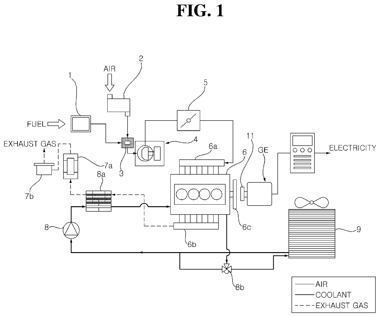
[0028]The present disclosure relates to a gas engine generation system for converting mechanical energy from an engine into electrical energy. More specifically, air, passing through an air cleaner, and fuel, passing through a zero governor, are mixed i...


PUM


Abstract

The present disclosure relates to a gas engine power generation system, having an engine configured to generate mechanical energy by burning an air-fuel mixture supplied from a mixer, which mixes air filtered by passing through an air cleaner, and fuel of a predetermined pressure which has passed through a zero governor, in which the gas engine power generation system converts the mechanical energy of the engine into electrical energy. The gas engine power generation system according to an embodiment of the present disclosure includes: an intake path having a first intake passage and a second intake passage in which air to be supplied to the mixer flows; an intake passage controller configured to open either one of the first intake passage or the second intake passage and to close the other one; a coolant pump configured to supply coolant to the engine; a radiator configured to dissipate heat of the coolant having passed through the engine; an intake air heater provided in the intake path at a portion where the second intake passage is formed, and configured to dissipate heat of the coolant having passed through the engine; a coolant passage controller configured to distribute the coolant, having passed through the engine, to the coolant pump, the radiator, and the intake air heater; and a controller configured to control operations of the intake passage controller, the coolant passage controller, and the coolant pump based on temperature of the coolant, having passed through the engine, and load information of the engine.

Description

CROSS-REFERENCE TO RELATED APPLICATION[0001]This application claims the priority from Korean Patent Application No. 10-2019-0120064, filed on Sep. 27, 2019, in the Korean Intellectual Property Office, the disclosure of which is incorporated herein by reference in its entirety.BACKGROUND OF THE INVENTION1. Field of the Invention[0002]The present disclosure relates to a gas engine power generation system, and more particularly to a gas engine power generation system, in which intake air, supplied to an engine, is heated using heat generated in the engine, thereby reducing pumping loss when the engine operates under part load conditions, and improving combustion efficiency.2. Description of the Related Art[0003]Generally, a power generation system is a device for converting mechanical energy, received from a power source, into electrical energy. Here, examples of the power source may include a turbine, a water turbine, a motor, a gas engine, and the like.[0004]In the case where a power...

Claims


Application Information

Patent Timeline
IPC IPC(8): F02M31/04H02K7/18
CPCF02M31/04H02K7/1815F02M31/10F01P2025/62F01P2060/02F01P2060/18F01P3/12F02B43/04F02B63/04F02M31/042F02M31/045Y02T10/30F01P7/167F02M29/04F01P5/10F02D41/18F01P2007/146F01P2025/08F02D2200/0406
Inventor SONG, JINGEUNCHOI, SONG
Owner LG ELECTRONICS INC
Why Eureka
Try Eureka