Control device for internal combustion engine

Inactive Publication Date: 2016-01-07
MITSUBISHI MOTORS CORP
View PDF12 Cites 7 Cited by
  • Summary
  • Abstract
  • Description
  • Claims
  • Application Information

AI Technical Summary

Benefits of technology

The invention aims to improve the fuel efficiency and acceleration performance of an internal combustion engine. It achieves this by adjusting the amount of air that enters the engine, which in turn affects the amount of exhaust gas that flows through the turbine of a supercharging unit. By controlling the intake air amount, the invention can increase the flow rate of exhaust gas bypassing the turbine and prevent unnecessary supercharging, reducing pumping loss and improving fuel efficiency. Additionally, the invention can increase the output torque of the engine by adjusting the intake air amount and the position of the waste gate valve, further improving acceleration performance. The invention also aims to prevent damage to the supercharging unit by adjusting the position of the waste gate valve to avoid surging or overspeed.

Problems solved by technology

However, in a case described above, where opening of the waste gate valve is controlled by a positive pressure type actuator, if the waste gate valve is required to be fully opened in a case where required supercharging pressure is low, for example, it is impossible to increase pressure of air to be introduced into the actuator.
As a result, it is difficult to allow the waste gate valve to be fully opened.

Method used


Image

  • Control device for internal combustion engine
  • Control device for internal combustion engine
  • Control device for internal combustion engine

Examples


Embodiment Construction

[0026]Hereinafter, an embodiment of the present invention will be described on the basis of the accompanying drawings.

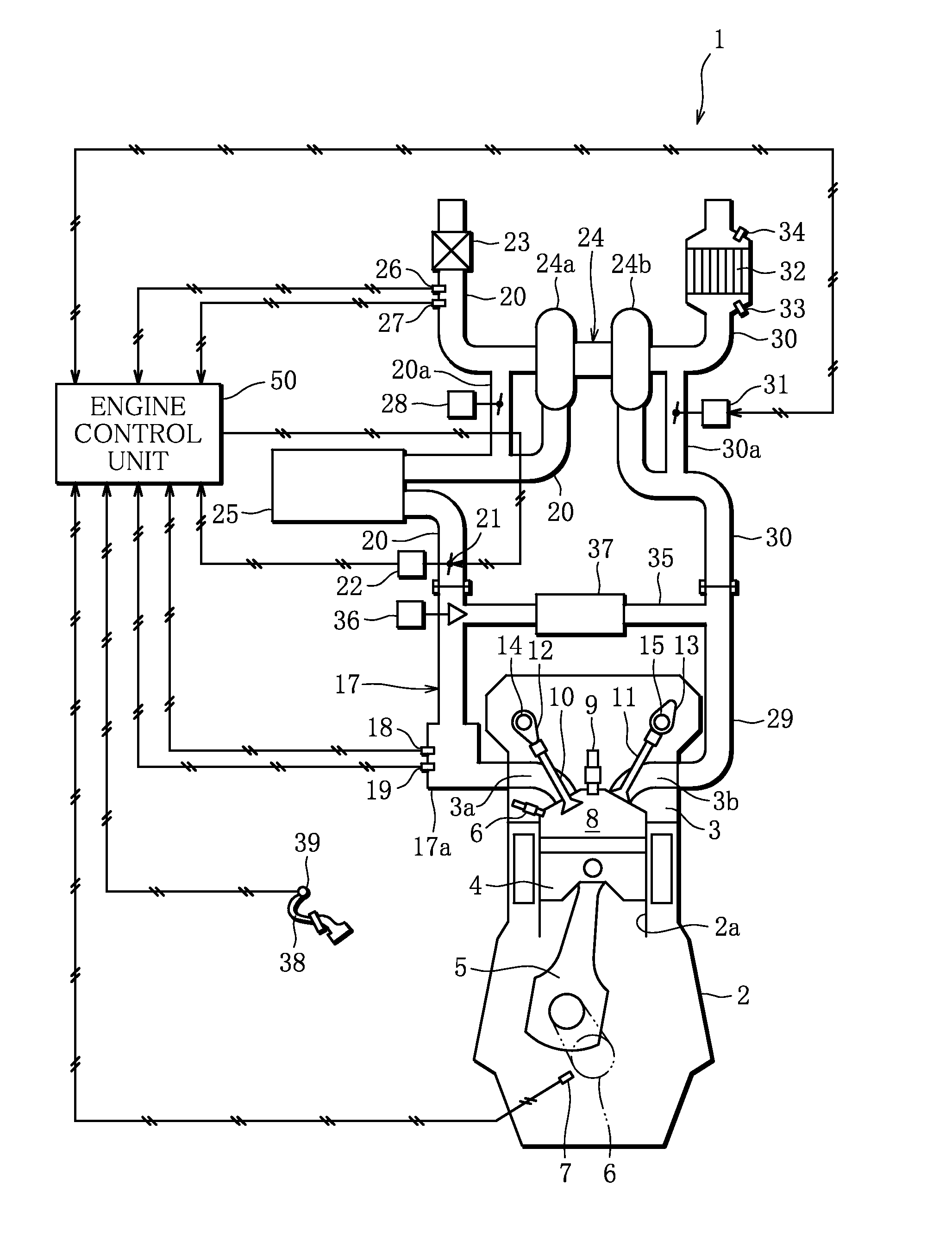
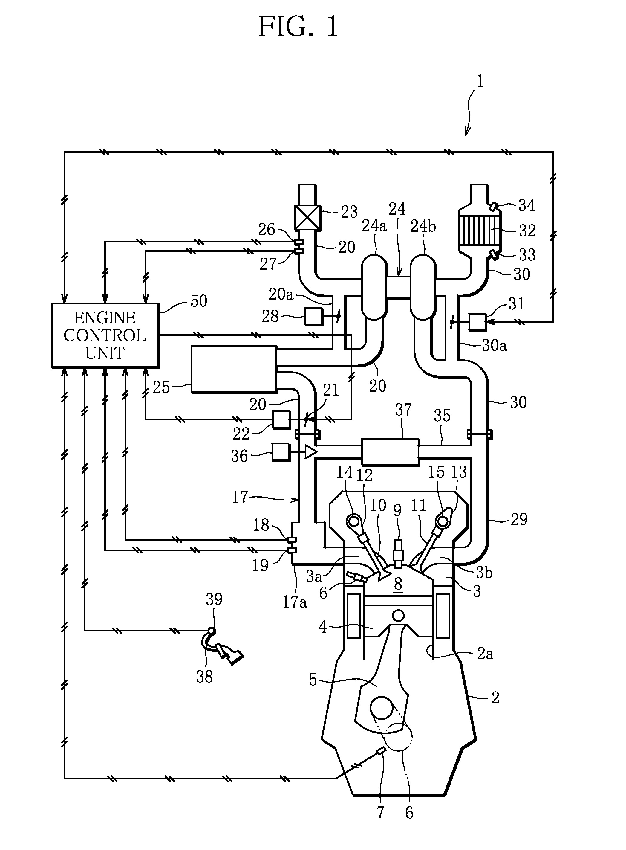
[0027]FIG. 1 is a schematic diagram of a direct-injection gasoline engine to which a control device for an internal combustion engine is applied (hereinafter referred to as an engine 1) (internal combustion engine).

[0028]As shown in FIG. 1, the engine 1 is a four-stroke in-line four-cylinder gasoline engine of a direct-injection type in which fuel is injected from a fuel injection valve 16 provided in a cylinder head 3 into a combustion chamber 8. FIG. 1 shows a longitudinal section of one cylinder of the engine 1. Since it is deemed that other cylinders have the same structure, they are not shown and there is no duplicated description on them.

[0029]As shown in FIG. 1, the engine 1 is composed of a cylinder block 2 on which the cylinder head 3 is mounted.

[0030]The cylinder block 2 is provided with a cylinder 2a. In the cylinder 2a, a piston 4 is vertically slidably p...


PUM


Abstract

In a case where a vehicle is in a steady running state or in a slow acceleration state, opening of an electric waste gate valve is set so that an actual air flow rate becomes minimum. Then, a feedback control is applied to opening of an electronically controlled throttle valve so that an actual amount of intake air generates output torque of an engine corresponding to an engine load. When the electronically controlled throttle valve is fully opened, while opening of the electronically controlled throttle valve is maintained, the feedback control is applied to opening of the electric waste gate valve so that output torque of the engine corresponds to an engine load, or an actual amount of intake air becomes a target amount of the intake air.

Description

TECHNICAL FIELD[0001]The present invention relates to a control device for an internal combustion engine, and more particularly to operation control of a waste gate valve.BACKGROUND ART[0002]Heretofore, an internal combustion engine has been provided with a supercharger such as a turbocharger to improve output performance and fuel efficiency. In such an internal combustion engine including a supercharger, there is provided a supercharging pressure adjustment device for adjusting pressure of intake air injected into a combustion chamber of the internal combustion engine, or supercharging pressure. The supercharging pressure adjustment device includes: a bypass passage that is provided in an exhaust pipe so that exhaust gas to be injected into an exhaust turbine of a turbocharger is allowed to detour downstream of the exhaust turbine; a waste gate valve for adjusting a flow rate of exhaust gas flowing to the bypass passage; a positive pressure type actuator for adjusting opening of th...

Claims


Application Information

Patent Timeline
IPC IPC(8): F02D41/00F02B37/18F02D41/10F02D41/18
CPCF02B37/18F02D41/18F02D41/10F02D41/0007F02D2200/0404F02D2200/0406F02D2200/0414F02D2200/1004Y02T10/12
Inventor MIHARA, NORIYUKI
Owner MITSUBISHI MOTORS CORP
Why Eureka
Try Eureka