Wireless communication device

a wireless communication and wireless technology, applied in disturbance protection, resonant antennas, instruments, etc., can solve the problems of high risk of ignition, high possibility of temporally continuous discharge of metal materials provided on the base material, and high risk of rfid tag or a portion of the product to which the rfid tag is attached, so as to prevent the melting and deformation of the wireless communication device or the portion of the product to which the wireless communication device is attached, and prevent ignition and combustion

Pending Publication Date: 2021-03-18
MURATA MFG CO LTD
View PDF5 Cites 5 Cited by
  • Summary
  • Abstract
  • Description
  • Claims
  • Application Information

AI Technical Summary

Benefits of technology

[0012]An object of the exemplary embodiments of the present invention is to provide a wireless communication device that prevents ignition and combustion even in a situation in which the wireless communication device is subjected to high-frequency power for heating a food item while being attached to the food item or the like.
[0014]According to the above structure and configuration, when the wireless communication device is irradiated with high-frequency power of an electromagnetic wave heating microwave band, a large current flows in the antenna pattern and heat is generated. Alternatively, heat is generated by discharge at a place of the antenna pattern where a potential difference is large. Due to this heat generation, a tensile stress is applied to the antenna pattern at a position which this expansion member is disposed adjacent to, so that the antenna pattern breaks. When the antenna pattern breaks, the above-described large current does not flow, and the heat generation is stopped. Alternatively, due to the breaking of the antenna pattern, the potential difference at the discharge position disappears or decreases, and the discharge is not maintained, so that the heat generation of the antenna pattern is stopped. In any case, the ignition of the base material does not occur. In this manner, melting and deformation of the wireless communication device or the portion of the product to which the wireless communication device is attached are also prevented.
[0015]According to the exemplary embodiments of the present invention, a wireless communication device is provided that prevents the ignition and combustion even when the wireless communication device is subjected to the high-frequency power for heating the food items while being attached to the food items or the like is able to be obtained.

Problems solved by technology

However, when the product to which the RFID tag is attached is heated using the microwave oven, the following problems sometimes arise.
Consequently, there is a risk that the RFID tag or a portion of the product to which the RFID tag is attached may ignite due to, for example, one or more of discharge at a place in which electric field strength is enhanced in the metal material, heat generation and sublimation of the metal material due to an overcurrent flowing in the metal material, and / or heat generation of the base material of the RFID tag.
In particular, since a high-power electromagnetic wave of about 3 kW is radiated inside a chamber of the microwave oven installed in the convenience store, and the RFID tag is heated at once immediately after the start of heating, there is a high risk of ignition depending on conditions.
However, the metal material provided on the base material has a high possibility of temporally continuous discharge, and there is currently no configuration that can surely prevent the risk of ignition of the base material and the possibility that the product catches fire.

Method used


Image

  • Wireless communication device
  • Wireless communication device
  • Wireless communication device

Examples


first exemplary embodiment

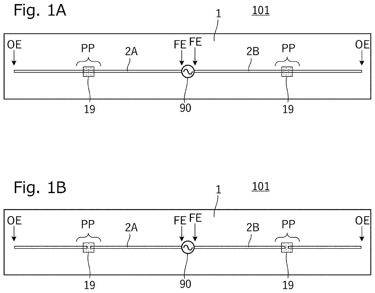
[0036]FIG. 1A is a plan view of an RFID tag 101 according to a first exemplary embodiment, and FIG. 1B is a plan view of the RFID tag 101 illustrating a state after a portion of an antenna pattern breaks.

[0037]As illustrated in FIG. 1A, the RFID tag 101 includes a base material 1 made of an insulator or a dielectric, antenna patterns 2A, 2B provided on the base material 1, and a feeding circuit 90 that supplies power to the antenna patterns 2A, 2B.

[0038]The RFID tag 101 of the present exemplary embodiment is configured to conduct wireless communication (i.e., transmission and reception) using a high-frequency signal having a frequency (e.g., a carrier frequency) of a communication signal in a UHF band. The UHF band is a frequency band of 860 MHz to 960 MHz. Here, the frequency of the communication signal in the UHF band is an example of a frequency of a communication signal in the present disclosure.

[0039]The feeding circuit 90, for example, is an RFIC element, an RFIC package, or t...

second exemplary embodiment

[0061]In a second exemplary embodiment, an RFID tag in which the shapes of an antenna pattern and an expansion member are different from the example illustrated in the first exemplary embodiment will be described.

[0062]FIG. 5A and FIG. 5B are plan views of an RFID tag 102 according to the second exemplary embodiment.

[0063]The RFID tag 102 illustrated in FIG. 5A and FIG. 5B includes a base material 1 made of an insulator or a dielectric, antenna patterns 2A, 2B provided on the base material 1, and an RFIC package 3 connected to the antenna patterns 2A, 2B. A plurality of expansion members 19 are provided on the base material 1.

[0064]As illustrated in FIG. 5A, the antenna patterns 2A, 2B have a meandering line shape and are each configured to extend, with the first antenna pattern 2A having the meandering line shape that meanders from a first land pattern 6a on which the RFIC package 3 is mounted while including a plurality of folded portions FP, and with the second antenna pattern 2B...

third exemplary embodiment

[0082]In a third exemplary embodiment, an example of an RFID tag different from the second exemplary embodiments in a shape of the expansion member and a position at which the expansion member is provided will be described.

[0083]FIG. 8A and FIG. 8B are plan views of an RFID tag 103 according to the third exemplary embodiment. FIG. 8C is a plan view of an RFID tag as a comparative example, without the expansion member 19.

[0084]As illustrated in FIG. 8A, the RFID tag 103 includes a base material 1 made of an insulator or a dielectric, antenna patterns 2A, 2B provided on the base material 1, and an RFIC package 3 connected to the antenna patterns 2A, 2B. An expansion member 19 is provided at a predetermined position on the base material 1.

[0085]As illustrated in FIG. 8A and FIG. 8B, the antenna patterns 2A, 2B have a meandering line shape and are each configured to extend, with the first antenna pattern 2A having the meandering line shape that meanders from a first land pattern 6a on w...


PUM


Abstract

An RFID tag is provided that transmits and receives a communication signal. The RFID tag includes a base material, an antenna pattern provided on the base material, and an expansion member. The expansion member is disposed adjacent to the antenna pattern and has a coefficient of linear expansion that is higher than coefficients of linear expansion of the antenna pattern. When the RFID tag is subjected to an electromagnetic wave heating microwave, and thus the temperature of each portion rises, the antenna pattern breaks at a position of the expansion member. With this configuration, ignition and combustion are able to be prevented even in a situation in which the RFID tag is subjected to high-frequency power for heating a food item while being attached to the food item.

Description

CROSS REFERENCE TO RELATED APPLICATIONS[0001]The present application is a continuation of PCT / JP2019 / 012088 filed Mar. 22, 2019, which claims priority to Japanese Patent Application No. 2018-136394, filed Jul. 20, 2018, the entire contents of each of which are incorporated herein by reference.TECHNICAL FIELD[0002]The present disclosure relates to a wireless communication device including an antenna, and, more particularly, to a wireless communication device such as an RFID (“Radio Frequency Identification”) tag that conducts near field communication through an induced electromagnetic field or an electromagnetic wave.BACKGROUND[0003]An RFID tag as a wireless communication device is used in various situations because the RFID tag communicates with a reader and writer and reading and writing operations of predetermined information are performed in a noncontact manner. For example, so-called self-checkout can be smoothly performed by attaching the RFID tag to all products. In addition, ...

Claims


Application Information

Patent Timeline
Patent Type & Authority Applications(United States)
IPC IPC(8): H01Q9/26G06K19/077H01Q1/00H01Q1/38
CPCH01Q9/26H01Q1/38H01Q1/002G06K19/077H01Q1/2225G06K19/07798
Inventor YAZAKI, HIROKAZU
Owner MURATA MFG CO LTD
Why Eureka
Try Eureka