Lidar system, operating method for a lidar system, and working device

Pending Publication Date: 2021-03-18
ROBERT BOSCH GMBH
View PDF0 Cites 0 Cited by
  • Summary
  • Abstract
  • Description
  • Claims
  • Application Information

AI Technical Summary

Benefits of technology

The present invention provides a LIDAR system that allows for reliable data exchange between the rotor and stator using simple means. This is achieved by developing a LIDAR system with a stator, rotor, transmitter optics, receiver optics, and communications unit for contact-free or wireless data transmission between the stator and rotor. The system uses optical communications channels for high data rate and large signal bandwidth, and a magneto-inductive data transmission is also utilized. The geometrical conditions of the system are simplified by making the communications channel parallel or at an angle with the axis of rotation. The compactness of the entire configuration of the communications unit is achieved by aligning an optical communications channel with the axis of rotation of the underlying LIDAR system.

Problems solved by technology

Particularly uncomplicated geometrical conditions are obtained in this way.
On the other hand, a particularly high degree of compactness of the entire configuration of the communications unit results if a respective optical communications channel is situated in alignment with the axis of rotation of the underlying LIDAR system.

Method used


Image

  • Lidar system, operating method for a lidar system, and working device
  • Lidar system, operating method for a lidar system, and working device
  • Lidar system, operating method for a lidar system, and working device

Examples


Embodiment Construction

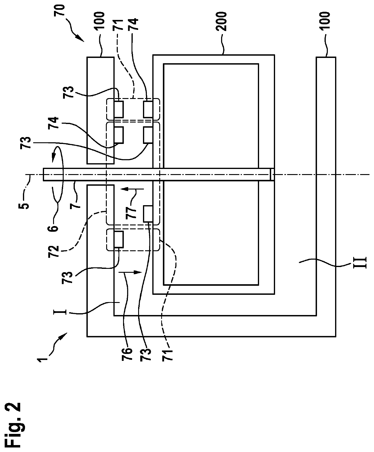
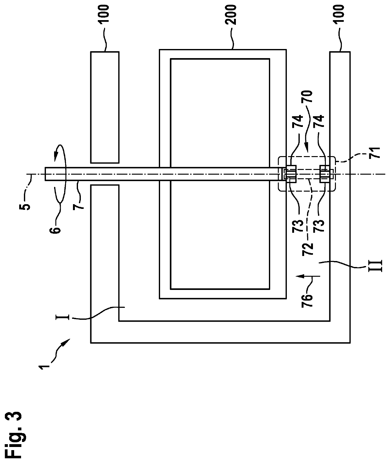
[0037]Below, exemplary embodiments of the present invention and the technical background are described in detail with reference to FIGS. 1 through 8. Identical and equivalent as well as similarly or equivalently acting elements and components are denoted by the same reference numerals. The detailed description of the denoted elements and components is not provided in all instances where they occur.

[0038]The illustrated features and further characteristics may be isolated from or combined with one another as desired without departing from the core of the present invention.

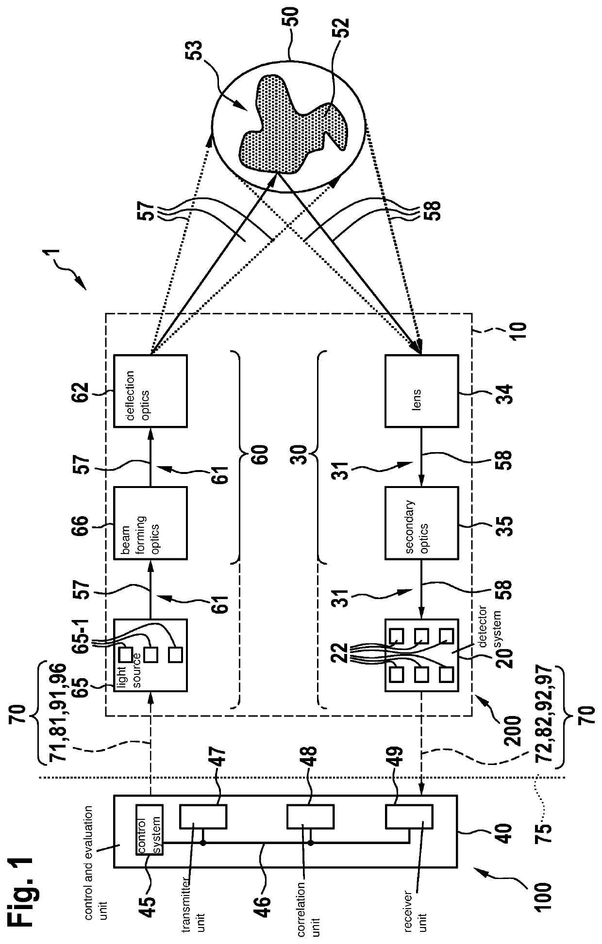
[0039]FIG. 1 shows a specific embodiment of LIDAR system 1 including an optical system 10 according to the present invention, in the form of a schematic block diagram.

[0040]As shown in FIG. 1, LIDAR system 1 has in its optical system 10 a transmitter optics 60 having an optical path 61, which is supplied by a light source unit 65 having light sources 65-1, in this instance in the form of lasers, for instance, and wh...


PUM


Abstract

A LIDAR system of the scanning type for the optical detection of a field of view a working device and / or a vehicle. The LIDAR system includes a stator, a rotor able to rotate about an axis of rotation in relation to the stator, a transmitter optics, a receiver optics and a communications unit for the contact-free data transmission between the stator and the rotor. At least part of the transmitter optics and / or part of the receiver optics is / are accommodated in the rotor, the communications unit has a first communications channel for the contact-free data transmission from the stator to the rotor, and a second communications channel for the contact-free data transmission from the rotor to the stator, and the first and the second communications channel are of a different nature.

Description

FIELD[0001]The present invention relates to a LIDAR system, in particular of the sampling or scanning type, to an operating method for such a LIDAR system, and a working device and in particular a vehicle.BACKGROUND INFORMATION[0002]When using working devices, vehicles and other machinery and systems, operating assistance systems or sensor systems are increasingly used for detecting the operating environment. In addition to video-based systems, radar-based systems or systems on the basis of ultrasound, light-based detection systems are used as well, e.g., what is known as LIDAR systems (light detection and ranging).[0003]In sampling or scanning LIDAR systems, primary light, after being generated, is routed across a field of view to be detected. So-called macro scanners which have a rotor and a stator are used for this purpose. The rotor accommodates at least part of the optics system, the sensor system and / or the light sources and is rotatable in relation to the stator with the aid ...

Claims


Application Information

Patent Timeline
IPC IPC(8): G01S7/481G01S17/931G01S7/00
CPCG01S7/4817G01S7/003G01S17/931G01S17/42
Inventor WORMS, KAIDRESCHMANN, MICHAEL
Owner ROBERT BOSCH GMBH
Why Eureka
Try Eureka