Railway brake system for a railway vehicle

a technology for brake systems and railway vehicles, applied in brake systems, brake components, brake cylinders, etc., can solve problems such as wear of linings, and achieve the effects of improving performance, simple, convenient and economical

Active Publication Date: 2021-03-18
FAIVELEY TRANSPORT AMIENS
View PDF0 Cites 0 Cited by
  • Summary
  • Abstract
  • Description
  • Claims
  • Application Information

AI Technical Summary

Benefits of technology

[0013]The invention concerns a braking system for a rail vehicle, with improved performanc

Problems solved by technology

It will be noted that the action of braking or, in other words, the tight application of the brake linings ag

Method used


Image

  • Railway brake system for a railway vehicle
  • Railway brake system for a railway vehicle
  • Railway brake system for a railway vehicle

Examples


Embodiment Construction

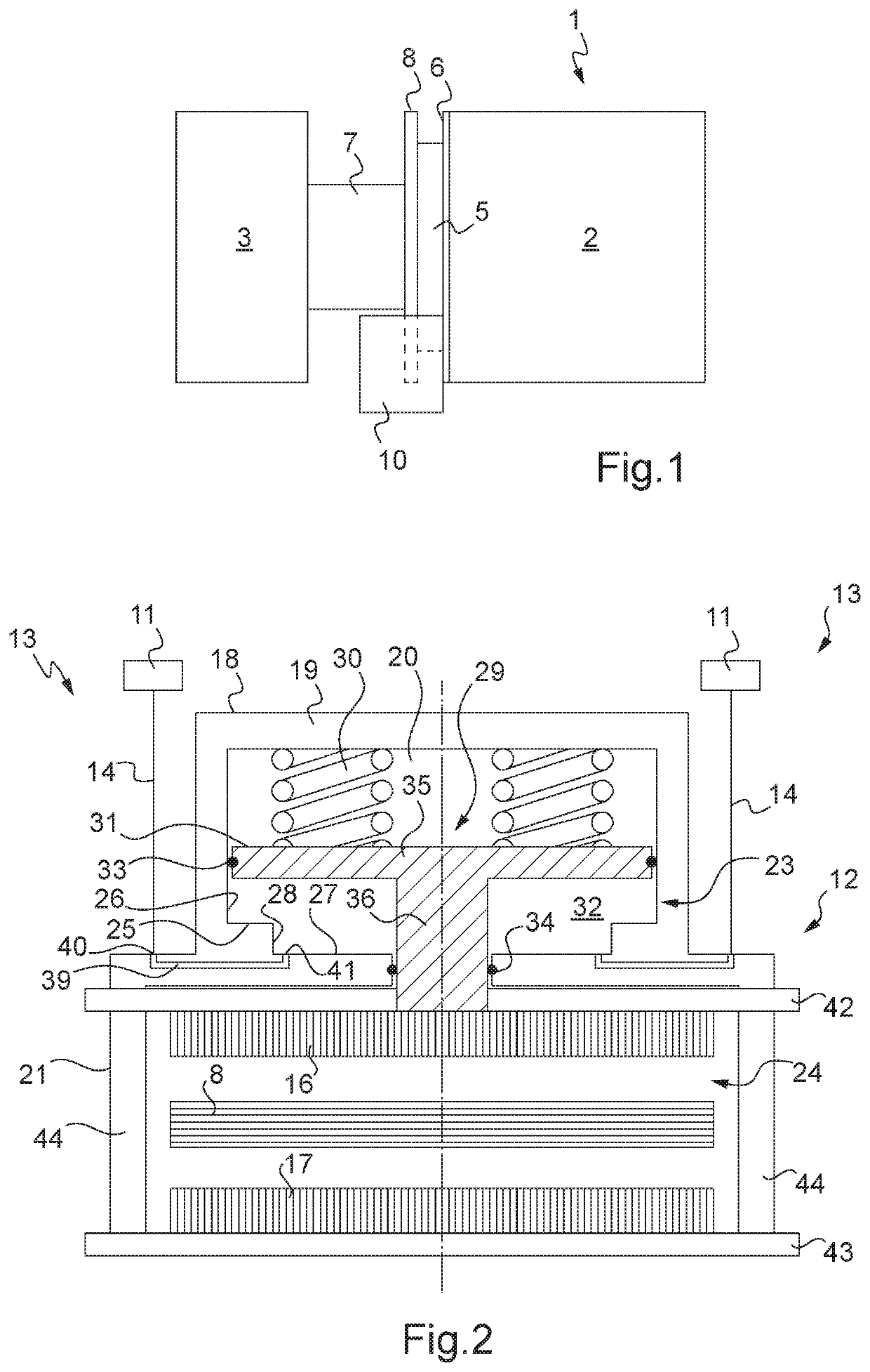
[0044]FIG. 1 represents partially and diagrammatically a rail vehicle 1, for example of subway type, provided with an electric traction driving system 2, in particular here a rotary electrical machine operating in drive mode, and an axle 3 bearing wheels (not shown) and which is connected to the driving system 2 for imparting rotation to the wheels via a coupling system 4.

[0045]This coupling system 4 here comprises a coupling plate 5 mechanically connected to a drive system flange 6 of the driving system 2, as well as a mechanism with a hub 7 connected at one end to the coupling plate 5 and at an opposite end to the axle 3.

[0046]The rail vehicle 1 is furthermore provided with a brake disk 8, here referred to as drive system disk, which is interposed between the coupling plate 5 and the mechanism with a hub 7.

[0047]It will be noted that in FIG. 1, the general direction of extension of the assembly formed by the driving system 2 and the coupling system 4 is substantially longitudinal,...


PUM


Abstract

Disclosed is a brake system for a railway vehicle, including linings each having at least one positioning member for mechanically fastening the linings in a predetermined position on the system with respect to a disc of the vehicle and a bearing face for tightly gripping the disc under the action of an actuator of the system, and at least one return member for separating the linings from the disc in order to release it when the linings are freed from the action of the actuator; each lining has at least one fastening member formed on an edge, the return member has two opposite end lugs connected to one another by an elastic portion and each mechanically fastened with a the fastening member, and the system is configured such that the fastening members and the end lugs are situated at a distance from the at least one positioning member.

Description

FIELD OF THE INVENTION[0001]The invention concerns the field of the braking of rail vehicles and more particularly rail vehicle braking systems for rail vehicles provided with a parking brake configured to act on a braking member of the vehicle, for example such as a disk brake, with the use of brake linings, in particular when the rail vehicle is stationary.TECHNOLOGICAL BACKGROUND[0002]Rail vehicles are generally equipped with service brake and / or parking brake calipers provided with a service brake and / or parking brake cylinder.[0003]This cylinder comprises a brake piston movable under the effect of the action of one or more springs and furthermore movable under the effect of a fluid under pressure.[0004]More specifically, this type of brake cylinder comprises a body in which and relative to which the brake piston is movable to act on the braking member via a thrust rod.[0005]The brake cylinder also comprises a cavity configured in the body and provided to receive the springs, as...

Claims


Application Information

Patent Timeline
IPC IPC(8): B61H5/00F16D65/095B60T13/38F16D55/227
CPCB61H5/00F16D65/095F16D2127/02F16D55/227B60T13/38B60T13/665B60T17/086B60T17/228F16D65/0975F16D2055/0029F16D2065/1396B60T17/08F16D2121/06F16D2200/0004F16D2200/0034F16D2250/0061F16D2250/0069F16D2250/0076
Inventor GONCALVES, CLAUDINOMAILLARD, LOUISLAURENT, FABRICECROSNIER, GUILLAUME
Owner FAIVELEY TRANSPORT AMIENS
Why Eureka
Try Eureka