
Light-emitting diode driving apparatus and light-emitting diode driver

a technology of light-emitting diodes and driving apparatuses, which is applied in the direction of cathode-ray tube indicators, static indicating devices, instruments, etc., can solve the problems of limiting the transmission speed of clock signals, data signals and clock signals, and limited clock signals transmission speed, so as to reduce power consumption and chip area

Active Publication Date: 2021-02-18
NOVATEK MICROELECTRONICS CORP
View PDF0 Cites 3 Cited by
  • Summary
  • Abstract
  • Description
  • Claims
  • Application Information

AI Technical Summary

Benefits of technology

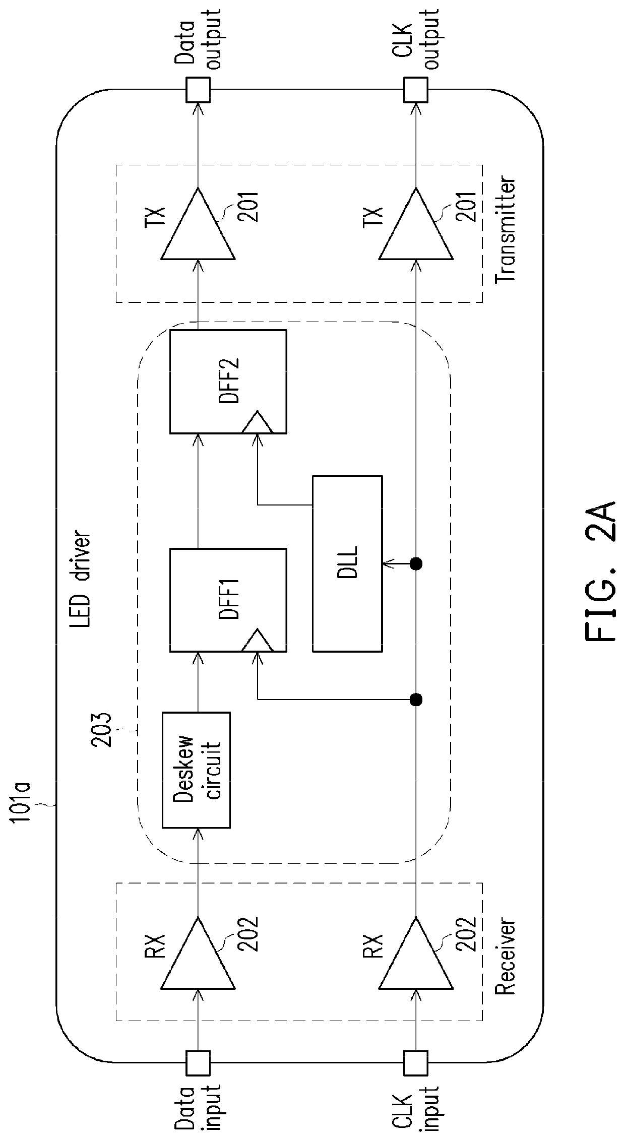
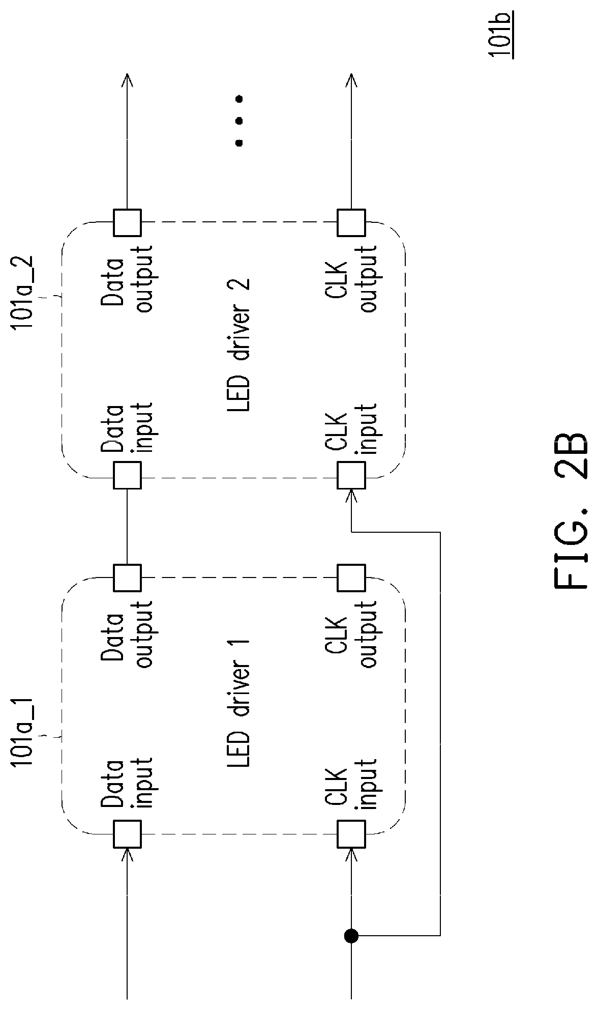
The patent describes a LED driving apparatus that reduces power consumption and chip area by sequentially enabling cascaded LED drivers without using FIFO memory. It achieves this by using a differential signal interface and de-skimming data and clock signals for the cascaded LED drivers. The apparatus also enhances the transmission speed of data and clock signals. Overall, the patent presents a way to improve the efficiency and speed of LED driving while saving costs.

Problems solved by technology

In the cascaded LED driver transmission interface, clock and data signals transmission speed are limited due to voltage swing range of the clock and data signals, parasitic capacitance of the clock signal lines, and environmental noise since the clock and data signals are single-ended signals.
In addition, skews between the clock signal and the data signal in each of the cascaded LED drivers may cause another issue and further limit the transmission speed of the data signal and the clock signal.

Method used


Image

  • Light-emitting diode driving apparatus and light-emitting diode driver
  • Light-emitting diode driving apparatus and light-emitting diode driver
  • Light-emitting diode driving apparatus and light-emitting diode driver

Examples


Embodiment Construction

[0026]Embodiments of the disclosure are described hereinafter with reference to the drawings.

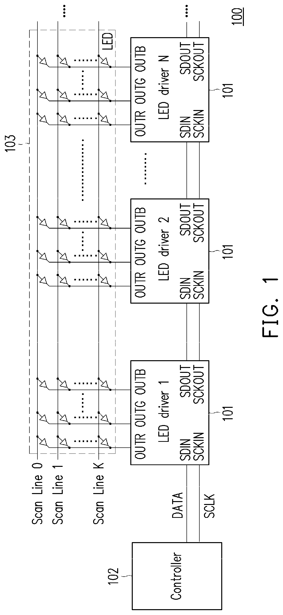
[0027]FIG. 1 is a schematic diagram of a LED driving apparatus 100 according to an embodiment of the disclosure. The LED driving apparatus 100 includes a plurality of LED drivers 101, a controller 102, and a plurality of LEDs 103. The plurality of LED drivers 101 include cascaded N stages LED drivers from LED driver 1 to LED driver N, and N is a positive integer. The controller 102 outputs an data signal DATA including a first data packet differential signal and a clock signal SCLK including a first clock differential signal to the first stage LED driver 1, the first stage LED driver 1 receives the first data packet differential signal and the first clock differential signal and outputs a second data packet differential signal and a second clock differential signal to the second stage LED driver 2, and the Mth stage LED driver M receives a Mth data packet differential signal and a Mth clock ...


PUM


Abstract

A LED driving apparatus with differential signal interfaces is introduced, including: N-stages LED drivers, wherein the first stage LED driver receives a first data packet differential signal and a first clock differential signal and outputs a second data packet differential signal and a second clock differential signal, the Mth stage LED driver receives a Mth data packet differential signal and a Mth clock differential signal and outputs a (M+1)th data packet differential signal and a (M+1)th clock differential signal.

Description

CROSS-REFERENCE TO RELATED APPLICATION[0001]This application is a continuation-in-part application of and claims the priority benefit of a prior application Ser. No. 16 / 866,551, filed on May 5, 2020, which claims the priority benefit of U.S. provisional application Ser. No. 62 / 885,828, filed on Aug. 13, 2019. This application also claims the priority benefit of Taiwan application serial no. 109127402, filed on Aug. 12, 2020. The entirety of each of the above-mentioned patent applications is hereby incorporated by reference herein and made a part of this specification.BACKGROUNDTechnical Field[0002]The disclosure relates to a light-emitting diode (LED) driving apparatus.Description of Related Art[0003]Generally, a cascaded LED driver transmission interface is used in a LED display system. In the cascaded LED driver transmission interface, clock and data signals transmission speed are limited due to voltage swing range of the clock and data signals, parasitic capacitance of the clock ...

Claims


Application Information

Patent Timeline
Patent Type & Authority Applications(United States)
IPC IPC(8): G09G3/32
CPCG09G3/32G09G2300/0857G09G2310/027G09G2310/08G09G2370/08G09G2370/14G09G2370/10G09G2320/0693G09G5/008
Inventor YEH, CHE-WEILIANG, KEKO-CHUNWANG, YU-HSIANGFANG, PO-HSIANGHUANG, JU-LIN
Owner NOVATEK MICROELECTRONICS CORP
Learn More