
Temporary Well Isolation Device

a well isolation device and well technology, applied in the direction of sealing/packing, earthwork drilling and mining, borehole/well accessories, etc., can solve the problems of complexity, cost and reliability of the well system, and achieve the effect of reducing degradation time and fast reaction tim

Active Publication Date: 2021-02-18
TERVES
View PDF0 Cites 7 Cited by
  • Summary
  • Abstract
  • Description
  • Claims
  • Application Information

AI Technical Summary

Benefits of technology

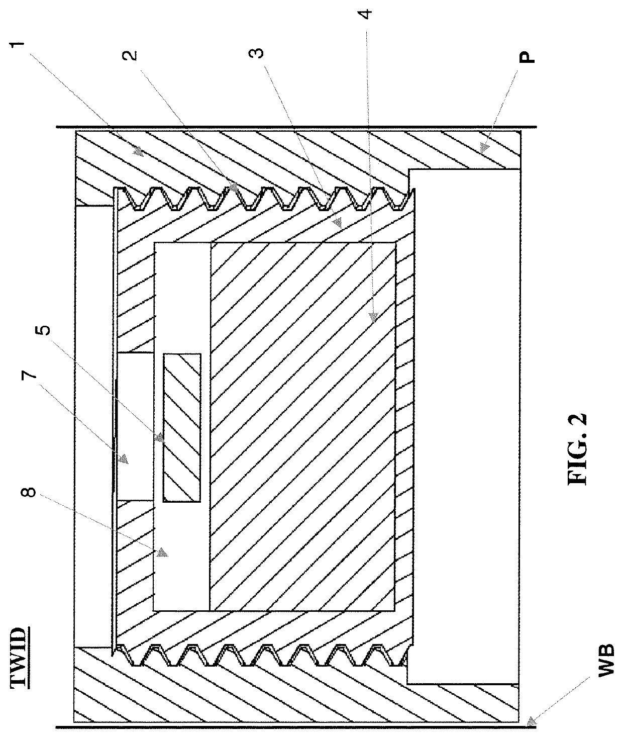
The present patent is about a temporary well isolation device that can be used in drilling wells. The device includes an outer housing, a barrier body, and one or more chemical materials. The chemical materials are located inside the barrier body and can cause the barrier body to corrode, dissolve, or degrade when exposed to fluids from the well. The device can be made in different sizes, shapes, and configurations, and can have controlled release properties. The chemical materials can accelerate the corrosion of the device and minimize the byproducts of corrosion. The device also includes one or more internal cavities filled with the chemical material to cause degradation, dissolvement, or dissolution of the device. The technical effect of this patent is to provide a temporary well isolation device that can safely and efficiently prevent fluid from entering the wellbore while still being able to be quickly and easily removed.

Problems solved by technology

For horizontal wells, where barriers may not fall to the bottom of the wellbore, some barriers are made of a frangible material or degrading material that degrades into components small enough so they do not prevent flow or restrict the casing inner diameter after a certain time.
For example, when the Magnum's Magnumdisk™ is used, a catcher must be installed further down the casing string which catches the frangible disc material before cementing is completed, thus adding to the complexity, cost and reliability of the well system.

Method used


Image

  • Temporary Well Isolation Device
  • Temporary Well Isolation Device
  • Temporary Well Isolation Device

Examples


example 1

[0080]A temporary well isolation device that is partially or fully formed of a degradable metal serves as a temporary seal in a wellbore. The temporary seal formed by the temporary well isolation device can be optionally designed or configured to allow a vertical casing section to be filled with fluid and / or gas (e.g., air, etc.) in a second section of the tool. Such fluid and / or air provides additional buoyancy to the temporary well isolation device; however, this is not required. The temporary seal can be designed or configured to form a seal between the gas- and water-filled sections until a differential pressure of 2,000 psi is applied to the surface of the temporary well isolation device, thereby causing a plug member in the temporary housing of the temporary well isolation device to burst and / or shear, which bursting and / or shearing of the plug member results in in the exposure of the chemical material contained in the temporary housing of the temporary well isolation device, ...

example 2

[0081]A temporary well isolation device is partially or fully formed of aluminum and configured to serve as a temporary seal in a tool. The temporary well isolation device includes a cavity that includes aluminum chloride. The temporary well isolation device includes a vertical casing section designed and configured to be filled with fluid (e.g., water, brine, etc.) and gas (e.g. air, etc.) and a temporary seal to seal a second section so that it is more buoyant; however, this is not required. The temporary well isolation device creates a seal between the gas- and fluid-filled sections until a differential pressure of 5,000 psi is applied to a surface on the tool, thereby causing a plug member in the body of the tool to burst and / or shear, which bursting and / or shearing of the plug member results in exposure of the chemical material (e.g., aluminum chloride) contained in the body of the tool to fluid, thereby producing an acid (e.g., hydrochloric acid). The production of the acid re...

example 3

[0082]A temporary well isolation device is partially or fully formed of a structural metal that serves as a temporary seal to allow a vertical casing section to be filled with fluid and gas (e.g., air) that is sealed in a second section so that it is more buoyant; however, this is not required. The temporary well isolation device creates a seal between the gas- and water-filled sections until a lance punctures the body of the plug member, which puncturing of the plug member results in the exposure of the material contained in the temporary housing of the temporary well isolation device, thereby causing the dissolving and / or degradation of the temporary housing of the temporary well isolation device within a certain time period (e.g., 30 minutes, one hour, two hours, etc.).


PUM


Abstract

A temporary well isolation device which has an axial passage that comprises a temporary housing having an internal cavity containing a chemical material and a temporary barrier or plug member that can be actuated by an external mechanism to allow fluid to flow into the internal chamber and contact the chemical material in the internal chamber. When the chemical material is exposed to fluid, the chemical material causes the temporary housing to corrode, dissolve, and / or degrade.

Description

[0001]The present disclosure claims priority on U.S. Provisional Application Ser. No. 62 / 886,682 filed Aug. 14, 2019, which is incorporated herein by reference.TECHNICAL FIELD OF THE DISCLOSURE[0002]The present disclosure pertains to a temporary well isolation device, particularly to a temporary well isolation device having an axial passage that comprises a temporary barrier with a cavity containing a chemical material that is actuated by an external mechanism, and more particularly to a temporary well isolation device having an axial passage that includes a temporary barrier, and wherein the axial passage connects to a self-contained cavity containing a chemical material, and wherein the temporary barrier can be actuated by an external mechanism to cause exposure of the chemical material in the self-contained cavity to a fluid which results in the chemical material causing the body of the temporary well isolation device to at least partially corrode, dissolve, and / or degrade.BACKGR...

Claims


Application Information

Patent Timeline
IPC IPC(8): E21B33/12E21B29/02
CPCE21B33/12E21B2200/08E21B29/02E21B34/063
Inventor SHERMAN, ANDREWDOUD, BRIANFARKAS, NICHOLASGILBERT, KURT
Owner TERVES
Learn More