
Anomaly detection method and anomaly detection device

a technology of anomalous frame and detection method, which is applied in the field of anomalous frame detection in communication networks, can solve the problem that the anomalous frame detection method disclosed in ptl 1 cannot be applied to the flexray in-vehicle network, and achieve the effect of safer in-vehicle network systems

Pending Publication Date: 2021-02-11
PANASONIC INTELLECTUAL PROPERTY CORP OF AMERICA
View PDF0 Cites 4 Cited by
  • Summary
  • Abstract
  • Description
  • Claims
  • Application Information

AI Technical Summary

Benefits of technology

This patent allows for detecting abnormal frames in a communication network that uses a time-triggered protocol. This results in a safer in-vehicle network system.

Problems solved by technology

Meanwhile, a CAN in-vehicle network has a security threat that an attacker accesses the bus and transmits an anomalous frame to falsely control an ECU.
Unfortunately, the anomaly detection method disclosed in PTL 1 cannot be applied to the FlexRay in-vehicle network, in which communications at the predetermined communication intervals allow a frame having a specific identifier (ID) to be received at constant intervals.

Method used


Image

  • Anomaly detection method and anomaly detection device
  • Anomaly detection method and anomaly detection device
  • Anomaly detection method and anomaly detection device

Examples


embodiment

[1. System Configuration]

[0054]The present embodiment describes an in-vehicle network system as an example of a communication network system, and an anomaly detection ECU as an example of an anomaly detection device included in the in-vehicle network system in Embodiment according to the present disclosure, with reference to the drawings.

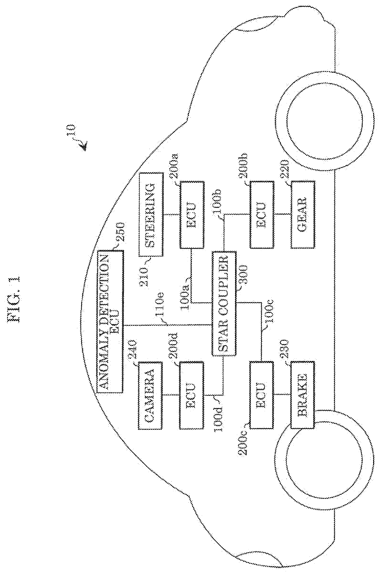
[0055]FIG. 1 is a block diagram illustrating an example of an overall configuration of in-vehicle network system 10 according to the present disclosure. In-vehicle network system 10 includes: buses 100a, 100b, 100c, 100d, and 100e used for communications established under a FlexRay protocol; ECUs 200a, 200b, 200c, and 200d and anomaly detection ECU 250 each connected to a corresponding one of the aforementioned buses; steering 210, gear 220, brake 230, and camera 240 each controlled by a corresponding one of the aforementioned ECUs; and star coupler 300 that connects the aforementioned buses to each other. ECUs 200a to 200d control a vehicle by tran...


PUM


Abstract

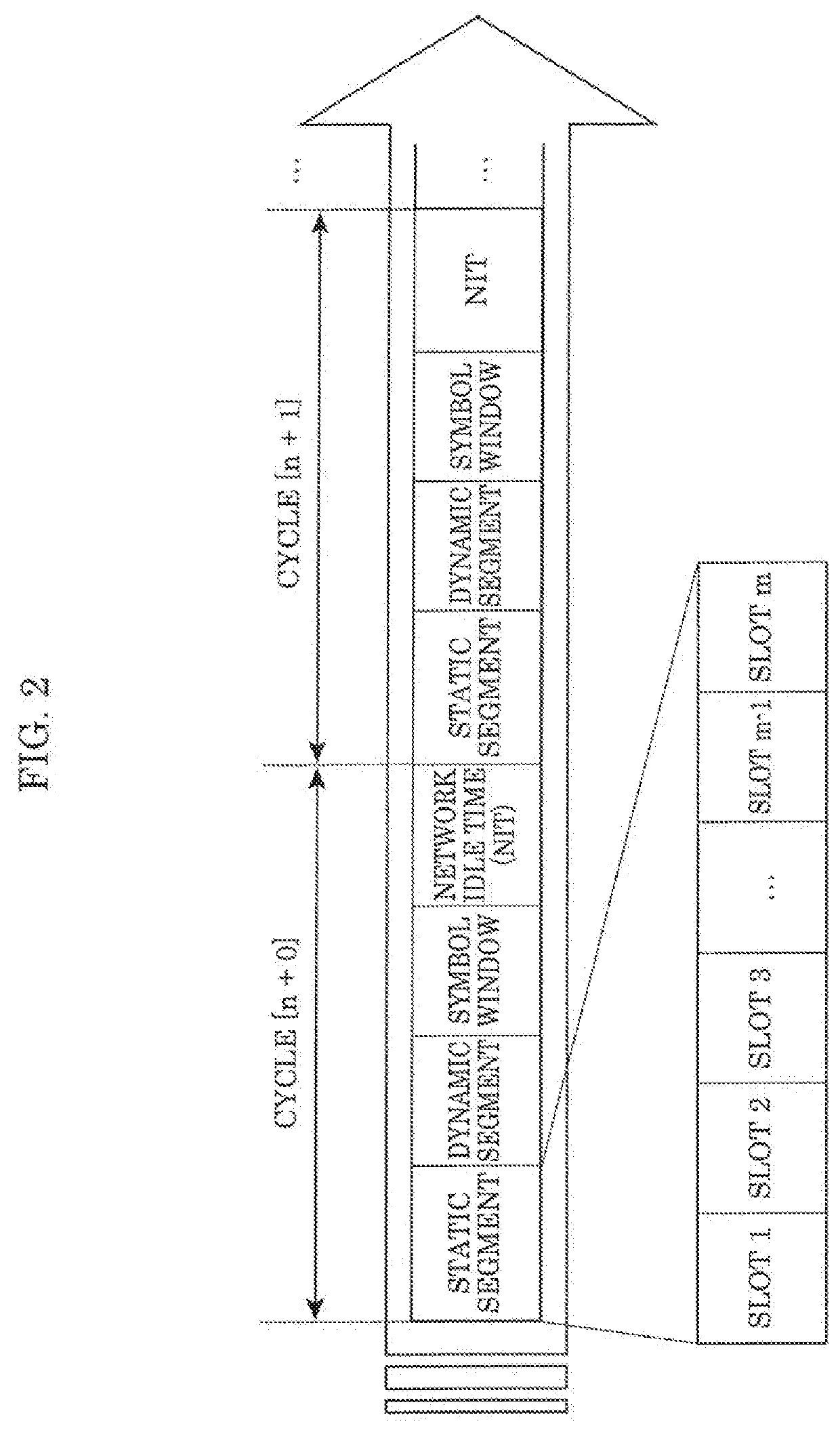
An anomaly detection device included in a communication network adopting a time-triggered protocol based on a time slot includes: a frame transceiver that receives frames; and an anomaly detector that detects an occurrence of an anomalous frame in accordance with a time slot among a plurality of time slots included in a cycle and the number of repeated cycles of the cycle for each frame. The anomaly detector detects an occurrence of an anomalous frame by verifying a statistic on the frames received while the cycle is repeated a predetermined number of times, which is at least once, against a rule indicating a reference range of the statistic.

Description

CROSS REFERENCE TO RELATED APPLICATIONS[0001]This application is a U.S. continuation application of PCT International Patent Application Number PCT / JP2019 / 029251 filed on Jul. 25, 2019, claiming the benefit of priority of PCT International Patent Application Number PCT / JP2018 / 028290 filed on Jul. 27, 2018, the entire contents of which are hereby incorporated by reference.BACKGROUND1. Technical Field[0002]The present disclosure relates to a technology of detecting an occurrence of an anomalous frame in a communication network.2. Description of the Related Art[0003]In recent years, an in-vehicle system of an automobile includes multiple devices called electronic control units (hereinafter, referred to as ECUs). A communication network that connects these ECUs is called an in-vehicle network. Many standards have been developed for such an in-vehicle network. Although one of the current most leading standards is a Controller Area Network (hereinafter, referred to as CAN [registered trad...

Claims


Application Information

Patent Timeline
IPC IPC(8): H04L29/06
CPCH04L63/1425H04L63/20H04L67/12H04W4/48H04L12/4035H04L2012/40241H04L2012/40273H04L12/40H04L2012/40208H04L12/40013G06F21/554
Inventor KISHIKAWA, TAKESHIUJIIE, YOSHIHIROHIRANO, RYOWAKABAYASHI, TOHRU
Owner PANASONIC INTELLECTUAL PROPERTY CORP OF AMERICA
Learn More