
Thermosiphon heat exchanger

Active Publication Date: 2021-02-11
DELTA ELECTRONICS INC
View PDF0 Cites 1 Cited by
  • Summary
  • Abstract
  • Description
  • Claims
  • Application Information

AI Technical Summary

Benefits of technology

The patent describes a heat exchanger that uses different materials to transfer heat between two systems. This design ensures that both the inside and outside of the system have enough heat exchangeability, without wasting money on excessive heat exchangeability. Overall, this design allows for efficient heat transfer at a lower cost.

Problems solved by technology

In other words, the heat exchange efficiency of the inner side and that of the outer side are different according to the different temperatures of the inner and outer sides, and the components on one of the sides causes ineffective heat exchangeability, and thus wastes part of the manufacturing costs.

Method used


Image

  • Thermosiphon heat exchanger
  • Thermosiphon heat exchanger
  • Thermosiphon heat exchanger

Examples


first embodiment

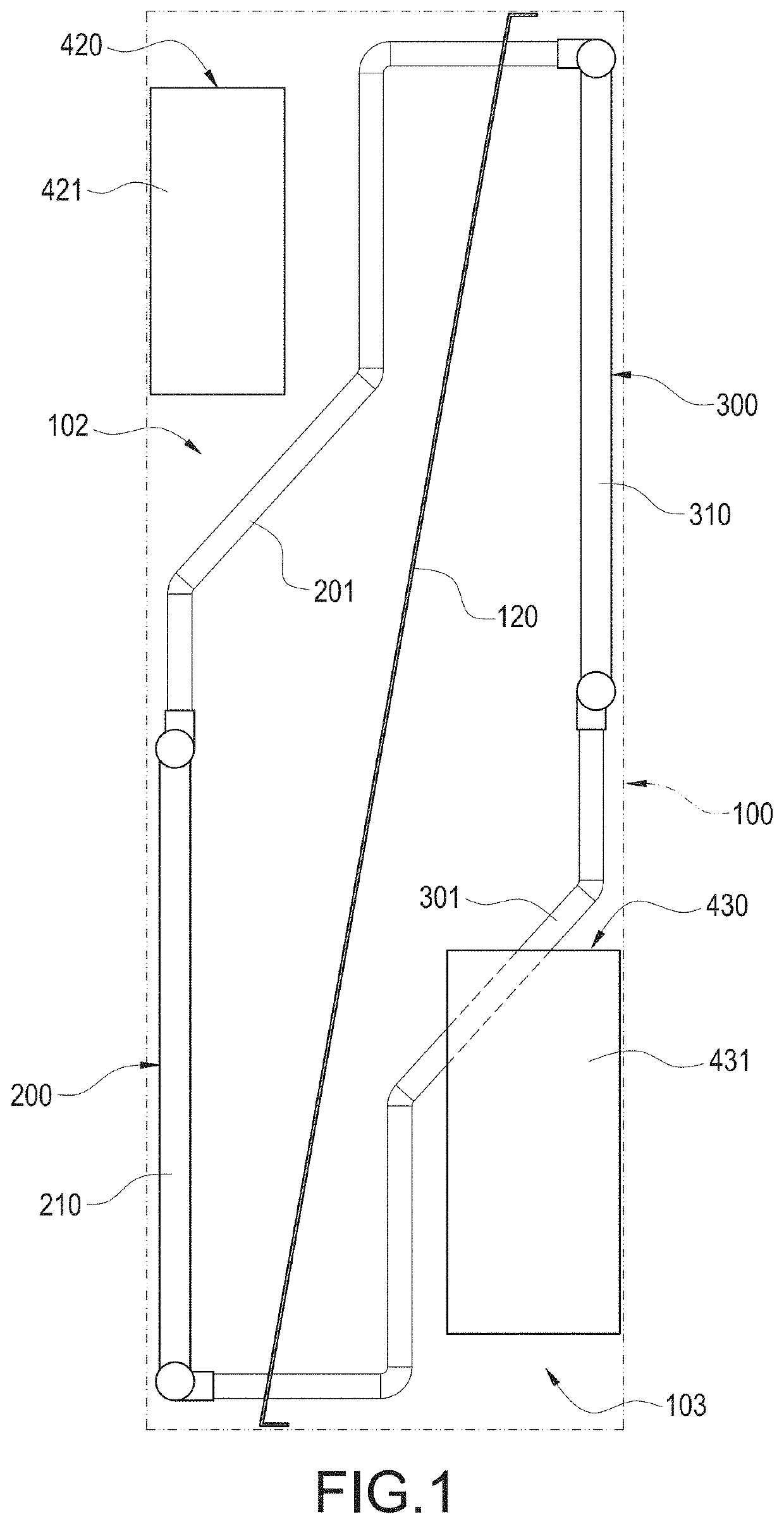
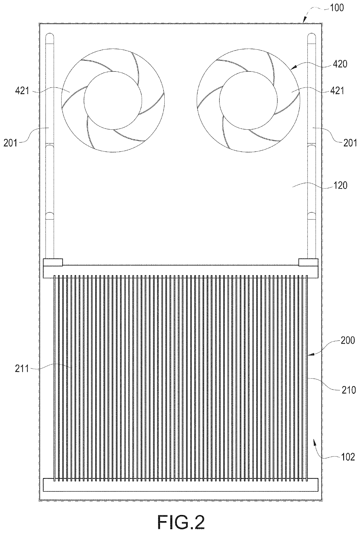
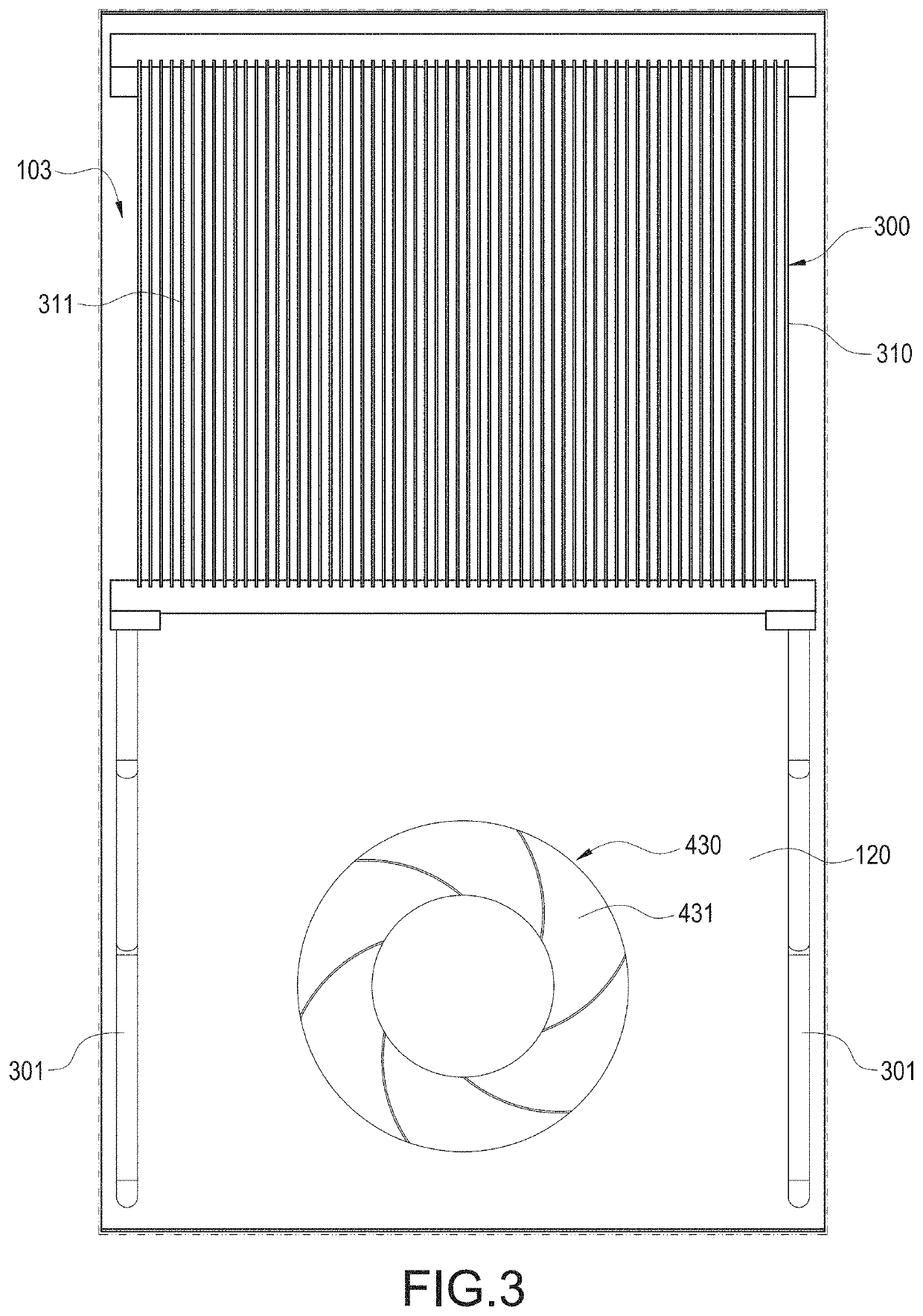
[0024]With reference to FIGS. 1 to 3 for a thermosiphon heat exchanger with asymmetrical internal and external heat exchange efficiencies in accordance with this disclosure, the thermosiphon heat exchanger comprises a chassis 100, an evaporation assembly 200, a condensation assembly 300, a first circulation fan module 420, and a second circulation fan module 430.

[0025]The chassis 100 is separated from an internal circulation chamber 102 and an external circulation chamber 103 by a partition panel 120. The evaporation assembly 200 is disposed in the internal circulation chamber 102. The condensation assembly 300 is disposed in the external circulation chamber 103 and horizontally positioned higher than the evaporation assembly 200, and the condensation assembly 300 and the evaporation assembly 200 are coupled and communicated with each other by a plurality of separated loops. It is noteworthy that the thermosiphon heat exchanger of this disclosure is not coupled to the compressor, so...

third embodiment

[0033]With reference to FIG. 6 for a thermosiphon heat exchanger in accordance with this disclosure, the thermosiphon heat exchanger comprises a chassis 100, an evaporation assembly 200a, a condensation assembly 300, a first loop, and a second loop, wherein the chassis 100 of this embodiment is the same as that of the previous embodiments, and thus its description thus will not be repeated.

[0034]The condensation assembly 300 has a condenser 310 disposed in the external circulation chamber 103.

[0035]The evaporation assembly 200a has a first evaporator 210a and a second evaporator 220a. The first evaporator 210a is disposed in the internal circulation chamber 102 and is horizontally positioned lower than the condenser 310. The second evaporator 220a is disposed in the internal circulation chamber 102 and is horizontally positioned lower than the condenser 310. Same as the previous embodiment, the condenser 310, the first evaporator 210a, and the second evaporator 210a of this embodime...


PUM


Abstract

A thermosiphon heat exchanger includes a chassis, an evaporation assembly and a condensation assembly. The chassis has an internal circulation chamber and an external circulation chamber separated from each other. The evaporation assembly is disposed in the internal circulation chamber. The condensation assembly is disposed in the external circulation chamber and horizontally positioned higher than the evaporation assembly, and the condensation assembly is coupled to the evaporation assembly by plural separated loops.

Description

CROSS-REFERENCE TO RELATED APPLICATIONS[0001]This application claims priority to China Patent Application No. 20201062179.0 filed Jun. 9, 2020, and is a Continuation-In-Part of pending U.S. patent application Ser. No. 16 / 881,847, filed on May 22, 2020 and entitled “HEAT-EXCHANGE APPARATUS”, which is a Continuation of U.S. Pat. No. 10,697,709B2, issued Jun. 30, 2020 and entitled “HEAT-EXCHANGE APPARATUS”, which claims priority of China Patent Application No. 201310536088.4, filed on Oct. 31, 2013. The entire disclosures of the above applications are all incorporated herein by reference.BACKGROUND OF THE INVENTION1. Technical Field[0002]The technical field of this disclosure relates to thermosiphon heat exchangers, and more particularly to a thermosiphon heat exchanger with an asymmetrical performance on internal and external heat exchanges.2. Description of Related Art[0003]Heat exchangers are often used for the purpose of dissipating heat from a sub-device cabinet, and this disclosu...

Claims


Application Information

Patent Timeline
IPC IPC(8): F28D15/02F28F13/06F28F19/00
CPCF28D15/0266F28D2015/0216F28F19/00F28F13/06F28D1/024F28D15/0275
Inventor CHEN, CHIA-WEIHUANG, WEI-ZHILIAO, KUN-CHIEH
Owner DELTA ELECTRONICS INC
Learn More