
Premixing apparatus

a technology of pre-mixing apparatus and pre-mixing liquid, which is applied in the direction of burners, fuel supply regulation, combustion types, etc., can solve problems such as failure of combustion, and achieve the effects of reducing the rotational speed of the fan, ensuring wind resistance performance, and reducing the minimum amount of combustion

Inactive Publication Date: 2021-02-11
RINNAI CORP
View PDF0 Cites 0 Cited by
  • Summary
  • Abstract
  • Description
  • Claims
  • Application Information

AI Technical Summary

Benefits of technology

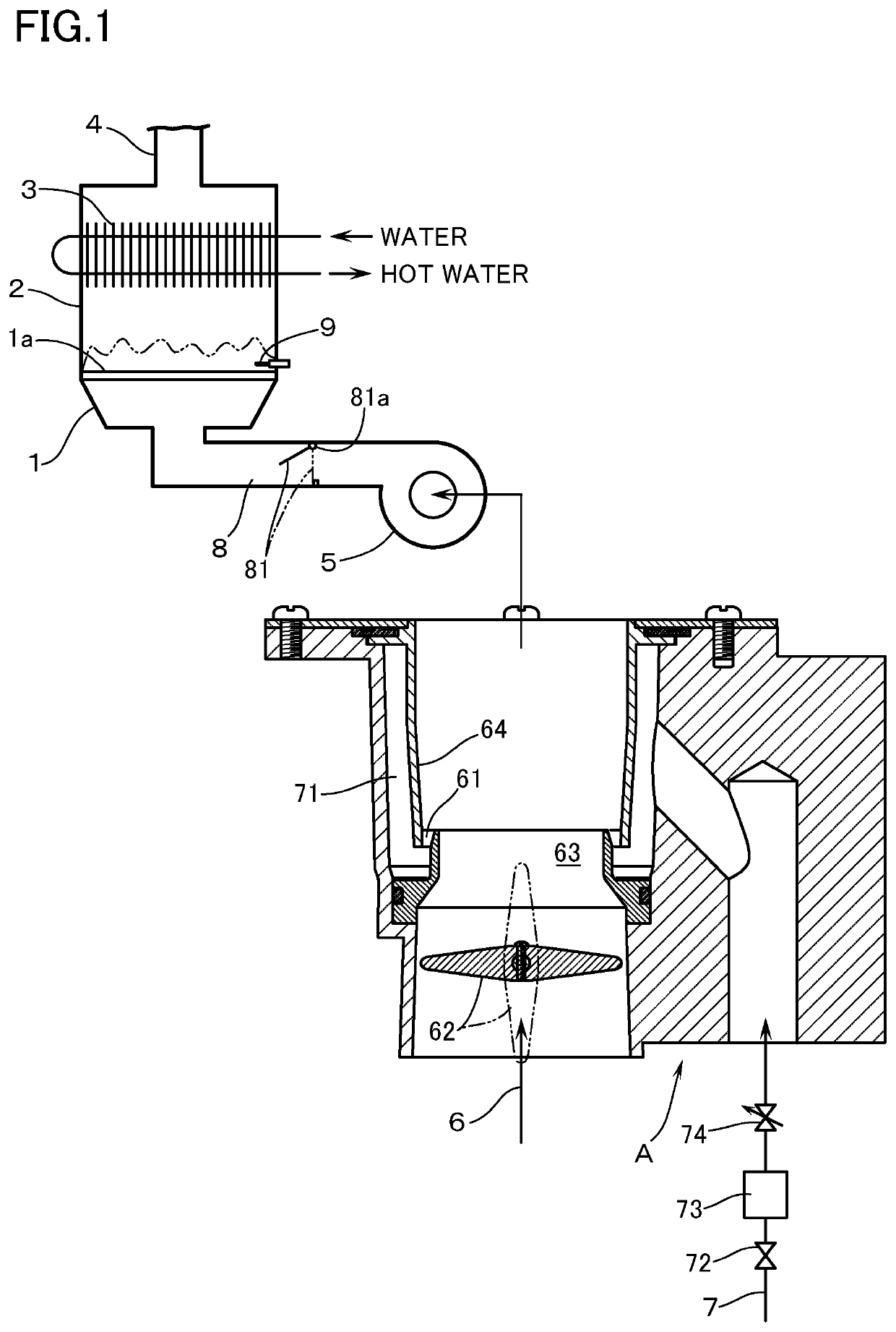
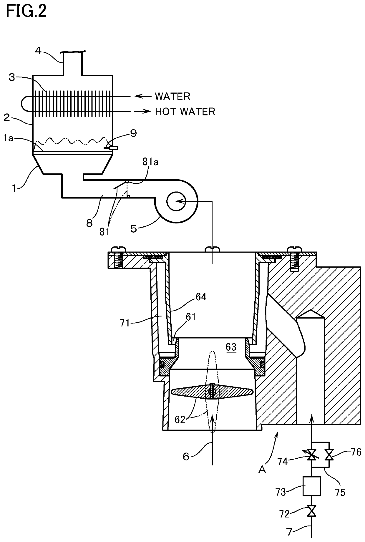
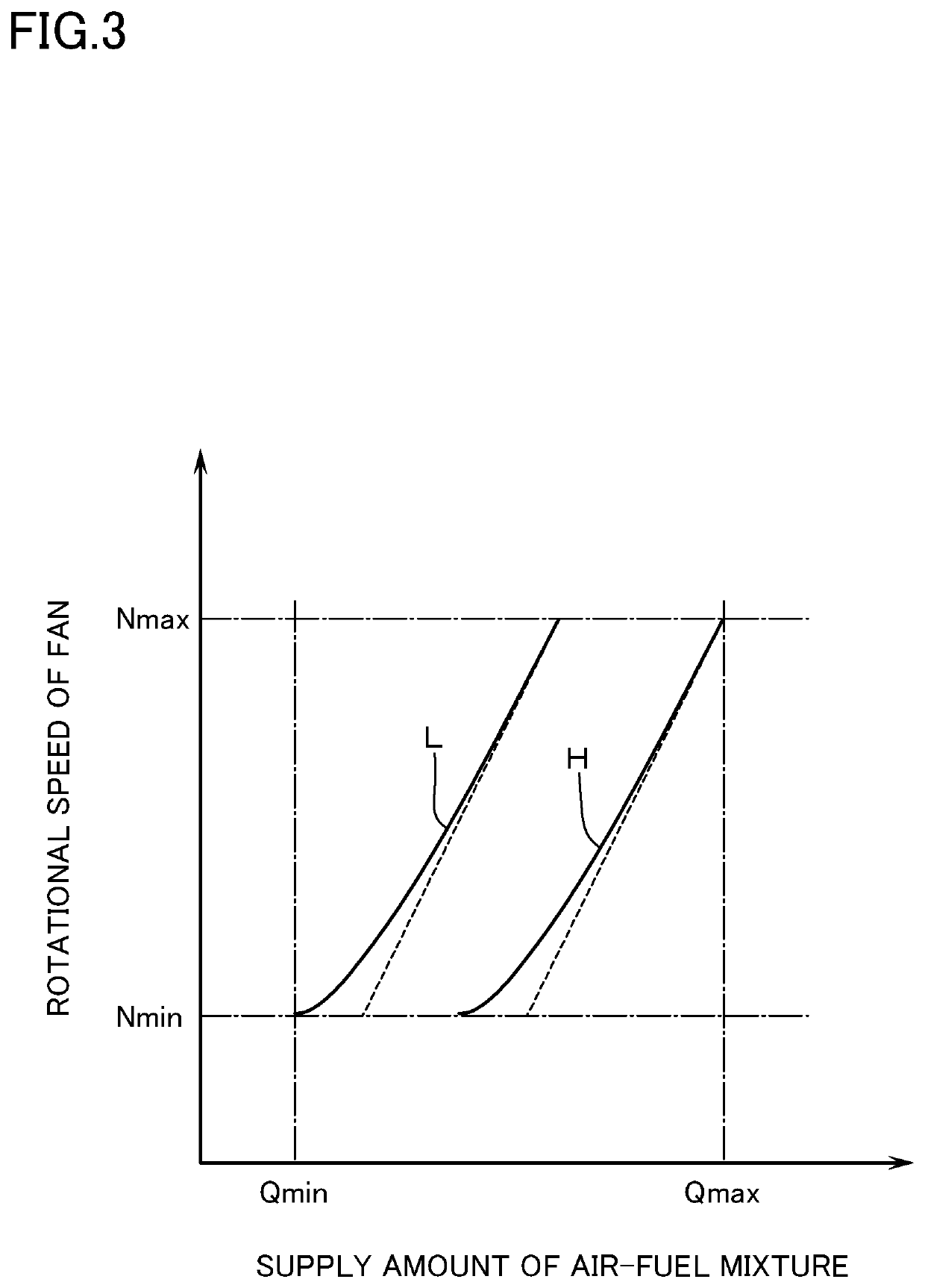
This patent is about a premixing apparatus used in fuel injection systems. The invention aims to prevent combustion failure due to fluctuations in fuel gas calorific value. By controlling the flow control valve, the excess air ratio of the air-fuel mixture can be kept constant. However, this may result in a relatively small amount of combustion at high fan rotational speeds, which causes a decrease in turndown ratio. To address this, the patent proposes the use of a swing valve that can adjust the passage area of the air-fuel mixture supply passage based on the fan rotational speed. This allows a relatively large amount of air-fuel mixture to be supplied even at high fan speeds, resulting in a larger turndown ratio. Additionally, the patent describes the use of a bypass passage with interposed on-off valve to vary the flow resistance in a controlled manner. This improves controllability without enlarging the opening degree of the flow control valve.

Problems solved by technology

Therefore, accompanied by the fluctuation of the calorific value of the fuel gas, the excess air ratio of the air-fuel mixture may fluctuate, thereby giving rise to the combustion failure.

Method used


Image

  • Premixing apparatus
  • Premixing apparatus
  • Premixing apparatus

Examples


first embodiment

[0025]Even in case the kind of gas of the fuel gas is changed, the excess air ratio of the air-fuel mixture can be made to the appropriate value by the control of the flow control valve 74. It is to be noted however that, in order to cope with the change to a gas with a largely different calorific value, it becomes necessary to largely change the flow resistance in a portion, on a downstream side of the zero governor 73, of the gas supply passage 7. In the arrangement of the first embodiment, it becomes necessary to make relatively wider the range of opening degree change of the flow control valve 74. For that purpose, the amount of change in opening degree per unit operation amount of the flow control valve 74 will be obliged to be made larger. As a consequence, the allowable error in the operation amount becomes slight, thereby deteriorating the controllability of the flow control valve 74.

second embodiment

[0026]On the other hand, even if the change width of opening degree of the flow control valve 74 is not so large, the flow resistance in a portion, on the downstream side of the zero governor 73, of the gas supply passage 7 can be varied over a wide range: by the opening degree change in the state in which the fuel gas does not flow through the bypass passage 75 as a result of closing the on-off valve 76; and by the opening degree change of the flow control valve 74 in a state in which the fuel gas flows through the bypass passage 75 as a result of opening the on-off valve 76. Therefore, the deterioration in the controllability of the flow control valve 74 due to enlargement of the range in opening degree change can be avoided.

[0027]Descriptions have so far been made of the embodiments of this invention with reference to the figures, but this invention shall not be limited to the above. For example, in the above-mentioned embodiments, in order to switch the capacity, the flow resis...


PUM


Abstract

A premixing apparatus for mixing air with a fuel gas in order to supply a burner with an air-fuel mixture through a fan, wherein a downstream end of a gas supply passage is connected to a gas suction part disposed in a portion, on an upstream side of the fan, of an air supply passage. The gas supply passage has interposed therein a zero governor for adjusting a secondary gas pressure to an atmospheric pressure. Even if the calorific value of the fuel gas may fluctuate, excess air ratio of the air-fuel mixture is arranged to be maintained at a constant value. The premixing apparatus is provided with: an excess air ratio detection device for detecting an excess air ratio of the air-fuel mixture; and a flow control valve interposed in a portion, on a downstream side of the zero governor, of the gas supply passage. The flow control valve is controlled such that the excess air ratio of the air-fuel mixture detected by the excess air ratio detection device becomes constant.

Description

TECHNICAL FIELD[0001]The present invention relates to a premixing apparatus for mixing air with a fuel gas in order to supply a burner with an air-fuel mixture through a fan.BACKGROUND ART[0002]Conventionally, as this kind of premixing apparatus, there is known one, e.g. in JP-A-2018-179447, in which a downstream end of a gas supply passage is connected to a gas suction part disposed in a portion, on an upstream side of the fan, of an air supply passage. The gas supply passage has interposed therein a zero governor for adjusting a secondary gas pressure to an atmospheric pressure. It is to be noted here that the supply amount of the fuel gas varies with a differential pressure between the atmospheric pressure which is the secondary gas pressure and a negative pressure inside the air supply passage. Since the negative pressure inside the air supply passage varies with the rotational speed of the fan, the supply amount of the fuel gas varies with the rotational speed of the fan, i.e.,...

Claims


Application Information

Patent Timeline
IPC IPC(8): F23D14/02F23D14/62F23D14/60
CPCF23D14/02F23D2200/00F23D14/60F23D14/62F23N1/022F23N5/123
Inventor NORITAKE, KATSUYATAKEUCHI, MASARUYOSHIMURA, KIMIHIRO
Owner RINNAI CORP
Learn More