
Microfluidic device and method for determining cell electrical barrier properties

a microfluidic device and cell technology, applied in the field of microfluidic devices and methods for determining cell electrical barrier properties, can solve the problems of electrode blocking the field of view, the hediger device requires a complex multi-step manufacturing process, and the failure rate of candidates in clinical trial stage, so as to minimize the resistance of the apical compartment, maximize the basolateral resistance, and improve the effect of sensitivity

Inactive Publication Date: 2021-02-11
UNIV OF SOUTHAMPTON
View PDF1 Cites 1 Cited by
  • Summary
  • Abstract
  • Description
  • Claims
  • Application Information

AI Technical Summary

Benefits of technology

The patent describes an electrode design that allows for accurate measurements of electrical properties of epithelial cell cultures with small amounts of electrolyte. An equivalent electric circuit was developed to study the effects of each circuit element on sensitivity, resulting in an optimal electrode geometry. This design maximizes basolateral resistance and minimizes apical compartment resistance, leading to better sensitivity and more uniform current distribution across the support membrane compared to prior art concentric electrode designs. The patent also provides a modular design for microfluidic devices that is simple to manufacture.

Problems solved by technology

One of the main costs associated with the development of new drugs is the rate of failure of candidates during the clinical trial stage.
The Hediger device requires a complex multi-step manufacturing process.
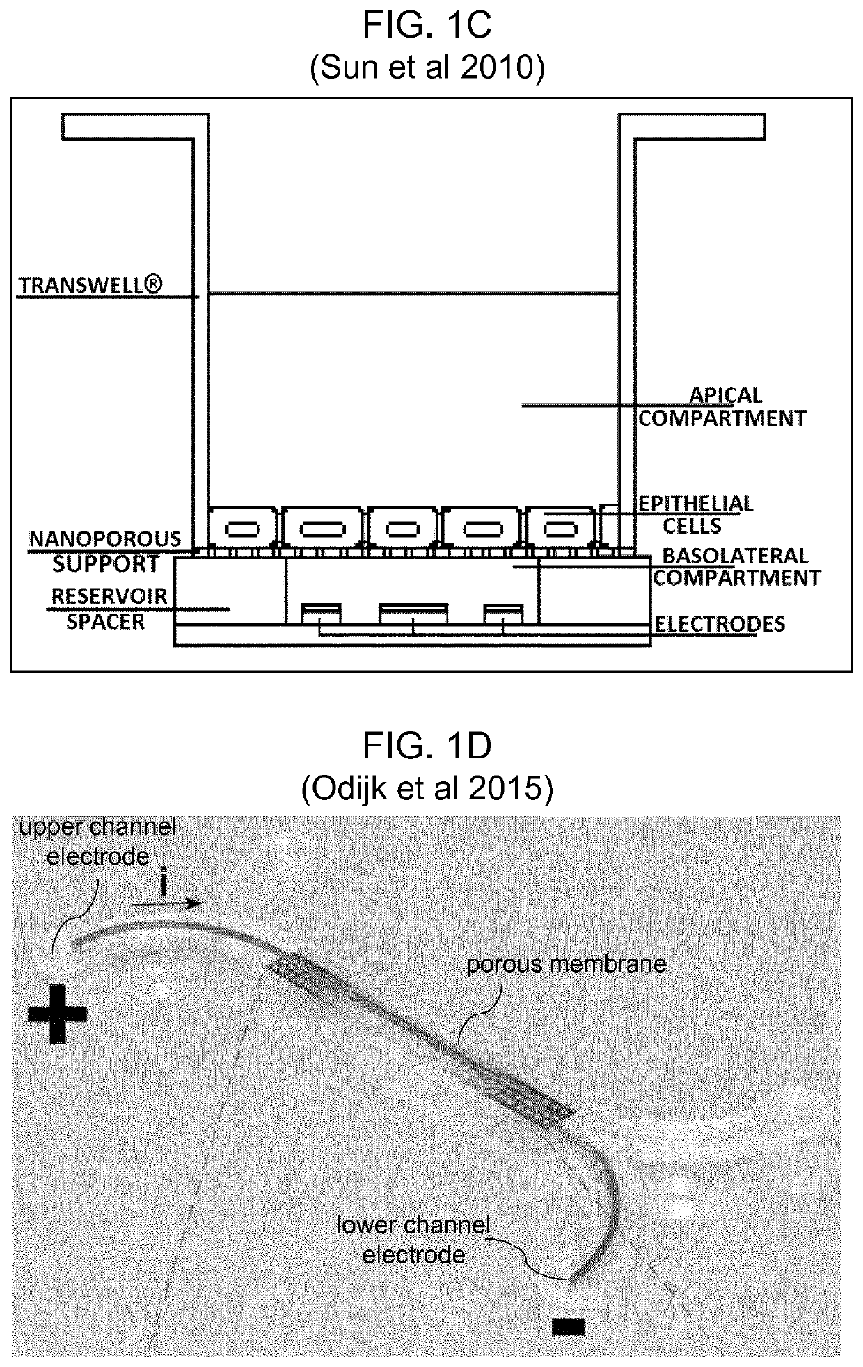
However, they stated that there would be major drawbacks of such an approach, namely the electrodes will block the field of view and device fabrication will be more complicated and costly.
A drawback of this system is the requirement to submerge the air-liquid culture with medium in order to perform the measurement.

Method used


Image

  • Microfluidic device and method for determining cell electrical barrier properties
  • Microfluidic device and method for determining cell electrical barrier properties
  • Microfluidic device and method for determining cell electrical barrier properties

Examples


Embodiment Construction

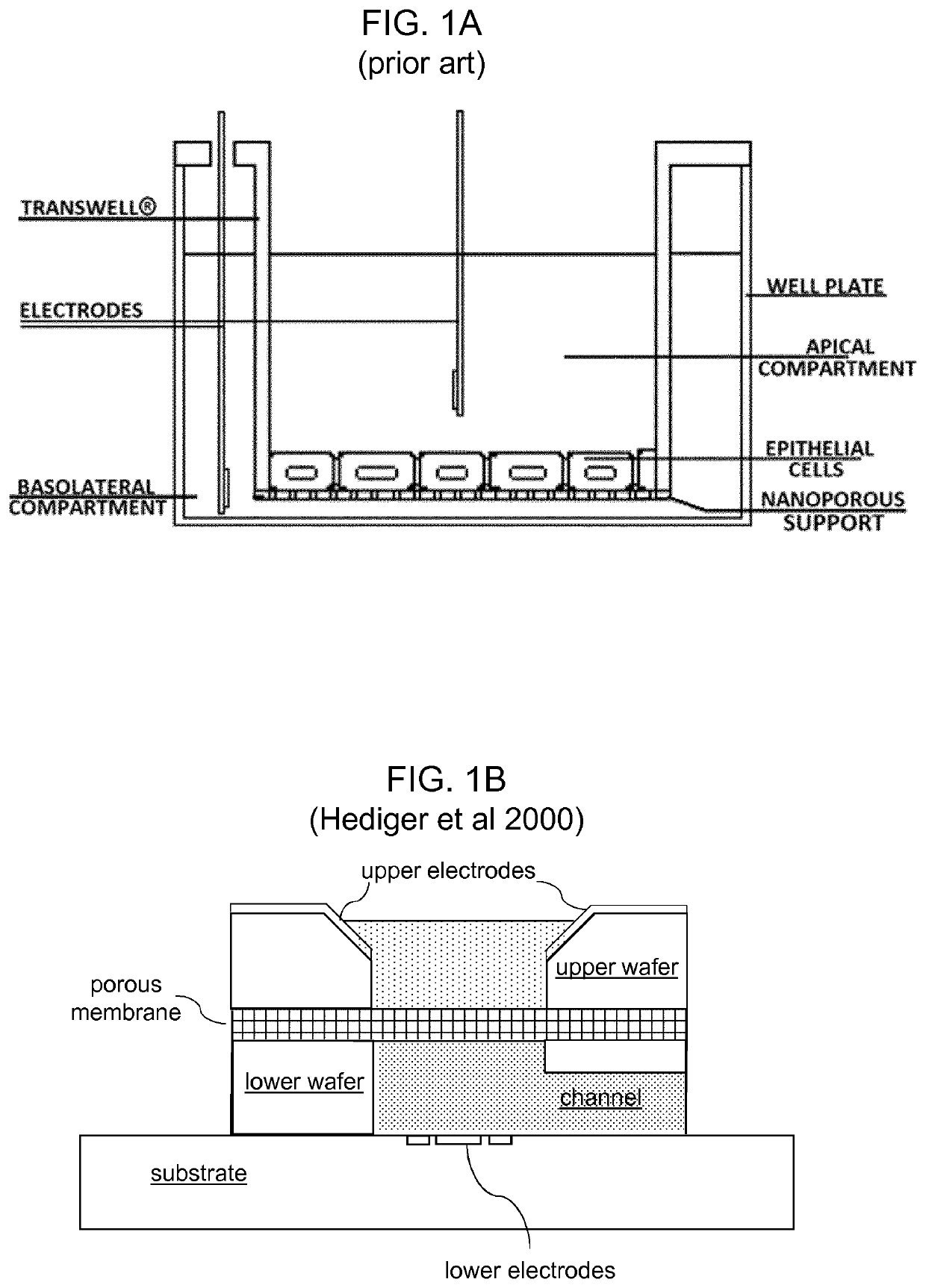
[0110]In airways of vertebrates, such as mammals, birds or reptiles, the epithelium is exposed to air on one side and liquid on the other. This Air-Liquid Interface (ALI) is a physiological condition that must be recreated in vitro in order to culture airway tissue, since the ALI is required to polarize and differentiate the cells which is pre-condition of culturing. The electrical resistance of the epithelial barrier formed at the ALI interface cannot be measured in situ using the classical trans-epithelium electrode configuration of FIG. 1A, because of the absence of a conducting electrolyte above the cell / tissue construct. This problem can be overcome by temporarily filling the air compartment with a liquid medium, but this is a disruptive and labour intense process.

[0111]Herein is described a simple system for in-situ electrical impedance spectroscopy (EIS) of epithelial cells cultured on porous supports which can be applied to fully submerged systems or for cells grown at the a...


PUM

PropertyMeasurementUnit
hole diameteraaaaaaaaaa
frequencyaaaaaaaaaa
diameteraaaaaaaaaa

Abstract

A microfluidic device is provided for studying primary human airway cells cultured at the air-liquid interface defined in the device by a barrier between an apical and basolateral compartment provided by a porous support for growing a cell layer. Within the chip, a liquid flow channel is provided through the basolateral compartment. Primary measurement electrodes are arranged widely spaced apart in the basolateral compartment to cause a significant component of electrical current flowing between them to flow via the cell layer. Secondary measurement electrodes are also provided to make comparative measurements which are used to deduce parameters that are relevant for the equivalent circuit model use for analysing the data obtained from the primary measurement electrodes. The microfluidic device has a modular construction of substrate, spacer and sidewall piece, with the electrodes being formed on the substrate, and the substrate and spacer co-defining the flow channel.

Description

FIELD OF THE INVENTION[0001]The invention relates to microfluidic devices and methods for determining cell electrical barrier properties.BACKGROUND[0002]One of the main costs associated with the development of new drugs is the rate of failure of candidates during the clinical trial stage. These costs could be reduced by the adoption of more accurate models with improved reliability at the preclinical stage. Epithelia are among the most biologically relevant features to be modelled, because they are the first tissue that has to be overcome for a drug to penetrate into the inner parts of any organ. Epithelia act as a barrier against the external environment by expressing protein complexes called tight junctions that confer to the tissue selective permeation properties towards ions and macromolecules. Tight junctions are the junctions which form between the abutting membranes of adjacent epithelial cells. The tight junctions form a selectively permeable barrier which restricts the free...

Claims


Application Information

Patent Timeline
Patent Type & Authority Applications(United States)
IPC IPC(8): C12M3/06C12M1/34G01N33/483
CPCC12M23/16G01N33/4836C12M41/46G01N33/5008G01N33/5438B01L3/502715B01L2300/0645B01L2300/0816B01L2200/0684B01L3/5027C12M1/00C12M35/02G01N13/00G01N33/483
Inventor MORGAN, HYWELREALE, RICCARDO
Owner UNIV OF SOUTHAMPTON
Learn More