Microfabrication method for optical components

Active Publication Date: 2021-01-14
NINGBO LITAS OPTICAL TECH CO LTD
View PDF0 Cites 0 Cited by
  • Summary
  • Abstract
  • Description
  • Claims
  • Application Information

AI Technical Summary

Benefits of technology

The present invention is a way to make a high-density optical connector ferrule that can align very precisely with optical fibers. We use a process called microfabrication to create a mold that has tiny holes for fibers and guide pins. These guide holes help align the optical connectors when they are mated. The result is a very precise connection that can handle multiple fibers in a small space.

Problems solved by technology

In part, the deteriorating performance with higher fiber counts is because conventional connectors are made with traditional polymer molding techniques; these molding techniques cannot achieve the precise alignment required.
However, it is very difficult to use molding to achieve a higher count 2-dimensional (2D) fiber holes accurately.
However, great challenges lie in the fabrication of such fiber connectors.
Because fiber holes and guide holes are formed by molding plastics around physical pins in the mold, when there is a high count 2D array of physical pins, it is very difficult to position these pins accurately and replicate the mold faithfully.
Although a 72-fiber multimode MPO connector in a 2D configuration (12×6) has been introduced by some manufacturers, its geometrical precision of fiber holes and guide holes is far inferior to 12-fiber multimode MPO connectors.
In addition, a SM fiber version of this connector is unavailable.
Higher fiber count MPO connectors not only have problems with SM fiber alignment tolerance, they also suffer from problems such as poor physical contact and sensitivity to dust and contaminants.
While the lens-based design allows this connector to operate without physical contact and ensure much more robust connection, insertion loss is high (0.8 dB insertion loss) even for multimode fiber.
Furthermore, MXC connectors are not availability for SM fiber.
The fiber ferrules in the MXC connectors are made by molding plastics, so these connectors suffer the same limitations as MPO connector ferrules.

Method used


Image

  • Microfabrication method for optical components
  • Microfabrication method for optical components
  • Microfabrication method for optical components

Examples


Embodiment Construction

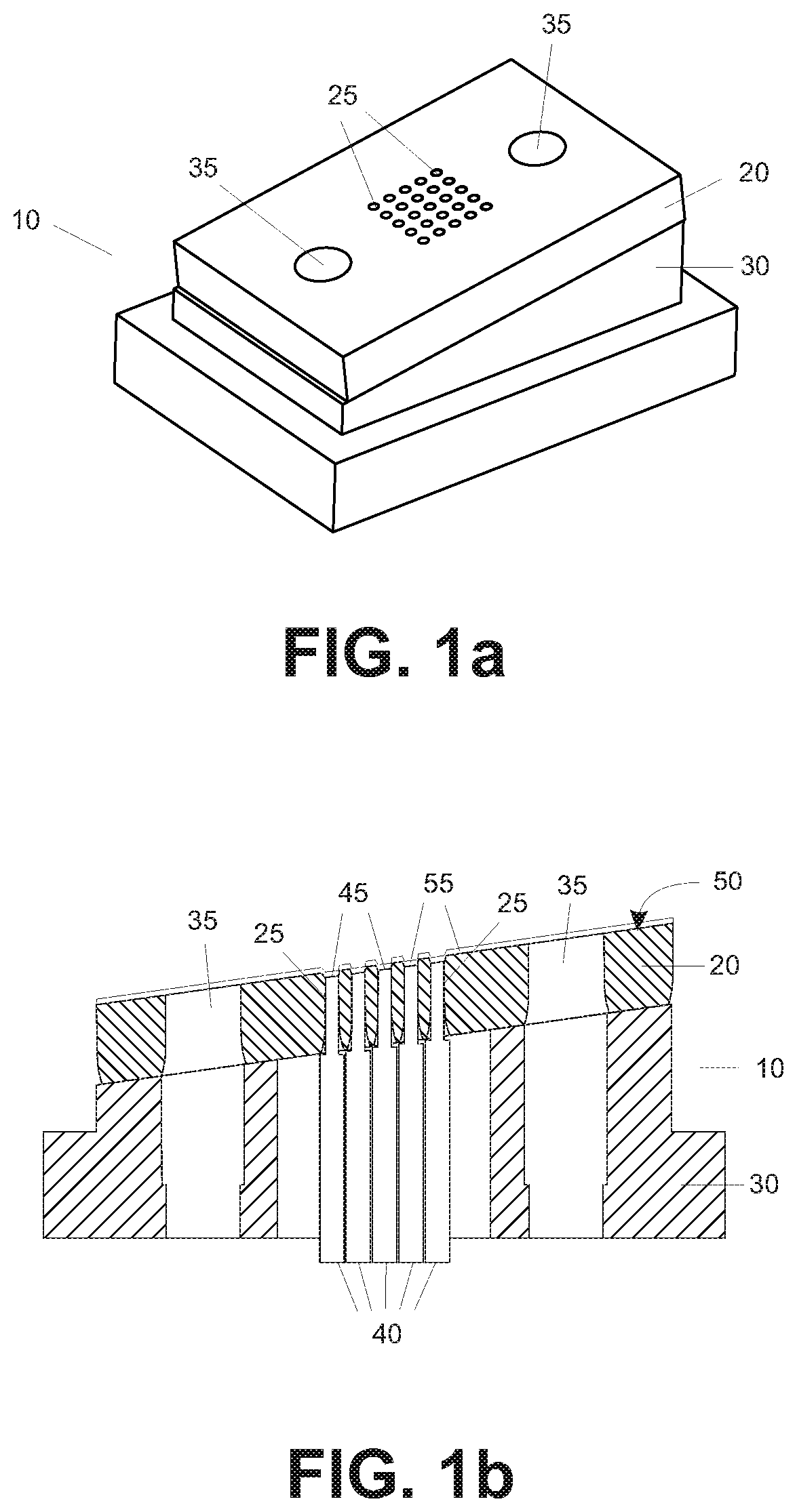
[0046]Turning to the drawings in detail, FIGS. 1a-1b depict perspective and cross-sectional views of a non-contact multi-fiber connector ferrule 10 formed by the method of the present invention.

[0047]The non-contact multi-fiber connector ferrule 10 includes a ferrule chip 20 and a ferrule pedestal 30. The ferrule chip 20 is significant because it provides the very high precision of this non-contact multi-fiber connector ferrule 10.

[0048]The ferrule chip 20 has at least four through holes, including two guide holes 35 and two fiber holes 25. Each guide hole 35 is dimensioned and configured to hold and align a guide pin. Each fiber hole 25 is dimensioned and configured to hold and align an optical fiber. Guide holes 35 facilitate passive alignment between mating multi-fiber optical fiber connectors.

[0049]While twenty-five fiber holes (5×5 array) are depicted for clarity of presentation, it is understood that substantially larger numbers of fiber holes may be formed in the multi-fiber ...


PUM

PropertyMeasurementUnit
Lengthaaaaaaaaaa
Densityaaaaaaaaaa

Abstract

A ferrule mold having a reverse-image of a through-hole array for optical fibers is formed. A non-polymeric ferrule material is deposited in the reverse-image mold, followed by removing the mold to create a multi-fiber connector ferrule having at least two fiber through-holes. An optical fiber is inserted in each through-hole until each fiber endface is positioned approximately even with a connection surface of the ferrule. A fiber recess for each of the optical fibers is formed such that each fiber is recessed from the multi-fiber ferrule connection surface by a distance of at least 0.1 micron. The recess may be formed by differential polishing of the non-polymeric ferrule and endfaces of the optical fibers. Alternatively, a layer of spacer material may be deposited over the multi-fiber ferrule connection surface. An antireflection coating is deposited over the ends of the recessed fibers.

Description

CROSS-REFERENCE TO RELATED APPLICATIONS[0001]This application claims priority from U.S. patent application Ser. No. 16 / 505,673, filed Jul. 8, 2019, the disclosure of which are incorporated by reference herein.FIELD OF THE INVENTION[0002]The present invention relates to a microfabrication method using a microfabrication mold, material deposition, material removal, etching, and coating to create an optical component such as a multi-fiber optical fiber connector.BACKGROUND[0003]Multi-fiber optical connectors are widely used by telecommunication system operators for various applications. Multi-fiber connectors are predominantly MPO fiber connectors. Commercially available MPO fiber connectors include fiber counts of, for example, 8, 12, 24, 48, or 72 fibers. For single mode (SM) fiber connectors which has much smaller fiber alignment tolerance than multimode fibers due to its much smaller fiber core, the most common fiber count of SM MPO connectors is 12 fibers today. Higher fiber count...

Claims


Application Information

Patent Timeline
IPC IPC(8): G02B6/38G02B1/11
CPCG02B6/3826G02B1/11G02B6/3854G02B6/3863G02B6/3865G02B6/3882G02B6/3672G02B6/3818G02B6/3885
Inventor JIAN, BENJAMIN B.
Owner NINGBO LITAS OPTICAL TECH CO LTD
Why Eureka
Try Eureka