Method for mounting an annular sealing element

Pending Publication Date: 2021-01-14
THYSSENKRUPP PRESTA AG +1
View PDF10 Cites 0 Cited by
  • Summary
  • Abstract
  • Description
  • Claims
  • Application Information

AI Technical Summary

Benefits of technology

The invention provides a method for assembling a sealing cord in a motor vehicle steering system. The method ensures that the sealing cord is positioned correctly and reduces mechanical stressing during assembly, which reduces the likelihood of function-impairing deformation of the sealing cord. The method is particularly advantageous for its efficient and cost-effective manufacturing operation and the importance of optimal assembly of the O-ring for safety.

Problems solved by technology

However, it is disadvantageous that, during stretching and application, the O-ring has to be stretched relatively far by the assembly fingers, and, as a result of the prescribed movement sequence, the O-ring may be subject to undesired mechanical stressing, twisting or torsion during assembly on the seal receptacle.

Method used


Image

  • Method for mounting an annular sealing element
  • Method for mounting an annular sealing element
  • Method for mounting an annular sealing element

Examples


Embodiment Construction

[0042]In the various figures, the same parts are always provided with the same reference designations, and will therefore generally also be named or mentioned only once in each case.

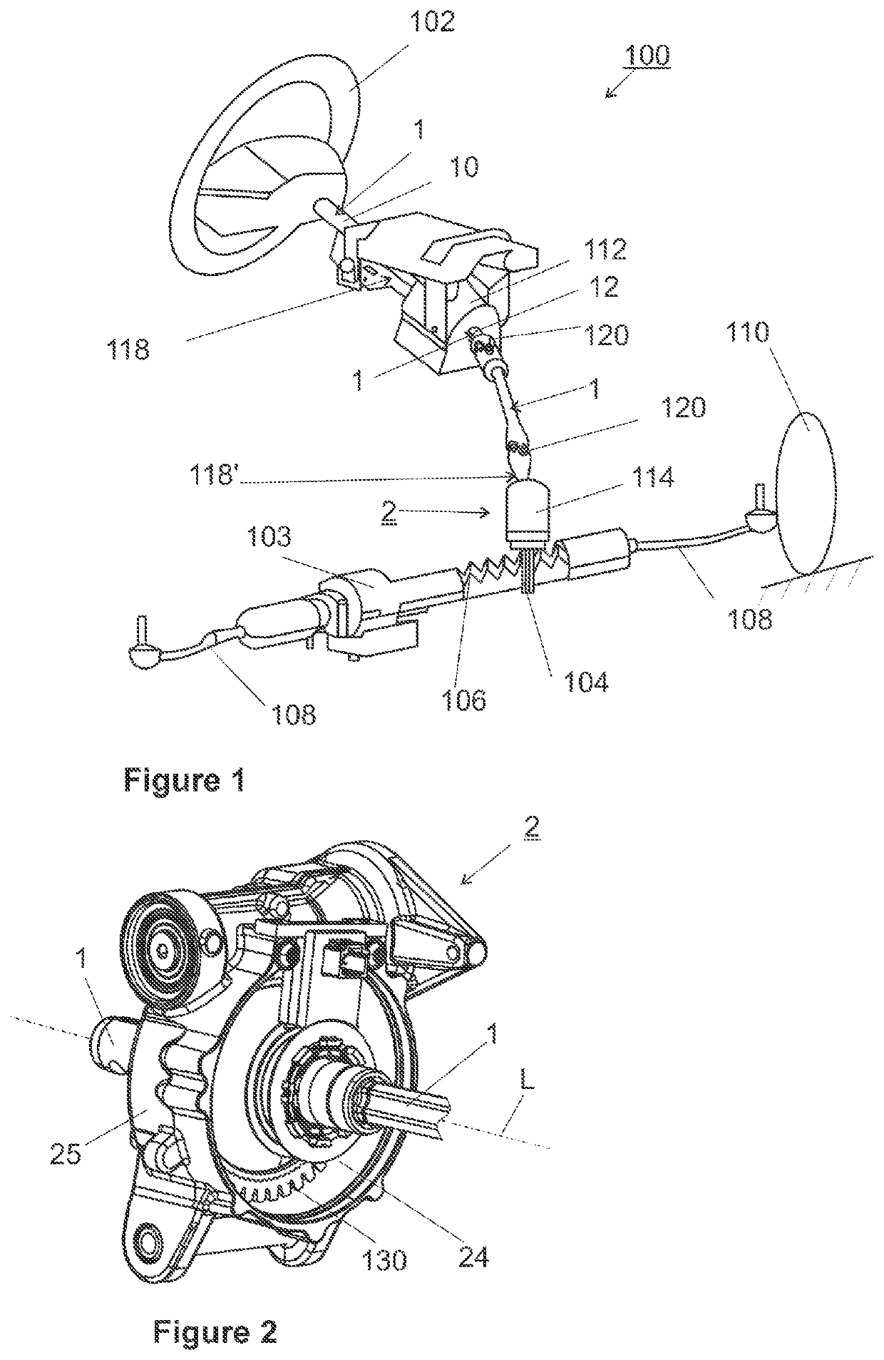
[0043]FIG. 1 schematically illustrates a motor vehicle steering system 100, wherein a driver can input a corresponding steering torque (steering moment) as steering command into a steering shaft 1 using a steering wheel 102. The steering moment is transmitted via the steering shaft 1 to a steering pinion 104, which meshes with a rack 106, which then in turn transmits the prescribed steering angle to the steerable wheels 110 of the motor vehicle by means of a displacement of the track rods 108.

[0044]An electrical power assistance means may be provided in the form of a power assistance means 112 coupled at the input side to the steering shaft 1, of a power assistance means 114 coupled to the pinion 104, and / or of a power assistance means 116 coupled to the rack 106. The respective power assistance means 11...


PUM


Abstract

A method for assembling an annular seal element, formed by a sealing cord which runs around an opening on a seal receptacle which runs around on the outside of a component. The method includes introducing two assembly fingers into the opening of the annular seal element, stretching the annular seal element by moving the assembly fingers apart from one another, with the formation of a cord portion of the sealing cord, the cord portion being freely tensioned between the assembly fingers, placing the freely tensioned cord portion onto the seal receptacle in a contact region, applying the annular seal element, by way of its opening, onto the seal receptacle, and removing the assembly fingers from the annular seal element. The assembly fingers are moved so as to follow the profile of the seal receptacle, to travel around the seal receptacle in opposite directions.

Description

PRIOR ART[0001]The invention relates to a method for assembling an annular seal element, which is formed by a sealing cord which runs around an opening, on a seal receptacle which runs around on the outside of a component,[0002]comprising the steps of:[0003]introducing two assembly fingers into the opening of the annular seal element,[0004]stretching the annular seal element by moving the assembly fingers apart from one another, with the formation of a cord portion of the sealing cord, said cord portion being freely tensioned between the assembly fingers,[0005]placing the freely tensioned cord portion onto the seal receptacle in a contact region,[0006]applying the annular seal element, by way of its opening, onto the seal receptacle,[0007]removing the assembly fingers from the annular seal element.[0008]To seal a component within a mating component which surrounds the latter externally, it is known to insert an annular seal element, such as, for example, an O-ring which is formed by...

Claims


Application Information

Patent Timeline
IPC IPC(8): F16J15/10
CPCF16J15/104B23P19/084F16C33/00F16C33/72B23P19/04B25J9/1682B23P19/047B23P19/08B25B27/14B25B27/0028B25J11/005
Inventor SCHÄDLER, SEBASTIANMÜNSTER, ANDREASSTADELMANN, MANUEL
Owner THYSSENKRUPP PRESTA AG
Why Eureka
Try Eureka