
Anti-interference section laser scanning imaging device for rail line fault diagnosis

A technology for laser scanning imaging and line faults, which is applied to measuring devices, railway car body parts, railway auxiliary equipment, etc. It can solve the problems of easy damage, difficult disassembly, and difficult fixing, so as to reduce crush damage and facilitate installation. and disassembly, to avoid the effect of pinching and crushing

Inactive Publication Date: 2020-11-17
CHONGQING TECH & BUSINESS UNIV
View PDF0 Cites 2 Cited by
  • Summary
  • Abstract
  • Description
  • Claims
  • Application Information

AI Technical Summary

Problems solved by technology

[0003] After the long-term operation of the railway track line, its interior is prone to damage, so the railway track needs regular maintenance. However, the shape of the interior of the railway track is not easy to detect. When recording the cross-sectional image of the rail or abandoned rail, the details of the cross-sectional image cannot be clearly recorded , leading to large loopholes in both logging and probing
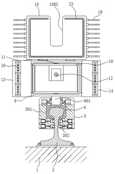
[0004] The application of the existing laser scanning imaging device in the maintenance of railroad tracks is relatively simple. When the imaging device is installed on the rail, it is easy to pinch and crush the outside of the rail due to its own weight, which makes the laser scanning imaging device impractical when used in rail maintenance

Method used


Image

  • Anti-interference section laser scanning imaging device for rail line fault diagnosis
  • Anti-interference section laser scanning imaging device for rail line fault diagnosis
  • Anti-interference section laser scanning imaging device for rail line fault diagnosis

Examples


Embodiment Construction

[0031] The following will clearly and completely describe the technical solutions in the embodiments of the present invention with reference to the accompanying drawings in the embodiments of the present invention. Obviously, the described embodiments are only some, not all, embodiments of the present invention.

[0032] In the description of the present invention, unless otherwise stated, the meaning of "plurality" is two or more; the terms "upper", "lower", "left", "right", "inner", "outer" , "front end", "rear end", "head", "tail", etc. indicate the orientation or positional relationship based on the orientation or positional relationship shown in the drawings, and are only for the convenience of describing the present invention and simplifying the description, rather than Indicates or implies that the device or element referred to must have a particular orientation, be constructed and operate in a particular orientation, and therefore should not be construed as limiting the...


PUM


Abstract

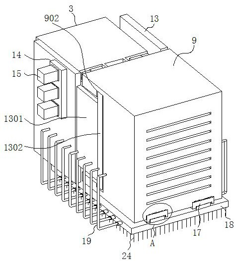
The invention discloses an anti-interference section laser scanning imaging device for rail line fault diagnosis, and relates to the technical field of rail line section laser scanning imaging, in particular to a foundation, a stock rail, a mounting sliding seat, an imager shell, a protective plate and a sealing plate. A stock rail is connected to the upper surface of the foundation through bolts,the installation sliding base covers the outer side of the upper portion of the stock rail, a matching groove is formed in the lower portion of the sliding groove, profiling cotton adheres to the inner side of the sliding groove, the imager shell is arranged on the outer side of one side of the upper edge of the installation sliding base, and the protection plates are installed on the two sides of the imager shell respectively. The sealing plate is arranged on one side of the bottom edge of the imager shell. The anti-interference section laser scanning imaging device for rail line fault diagnosis is easy to install, fix and disassemble, can realize sealing, can perform rapid scanning corresponding to the section of the rail, and cannot be damaged by clamping and pressing due to dead weight when being installed on the rail.

Description

technical field [0001] The invention relates to the technical field of laser scanning and imaging of rail line cross-sections, in particular to an anti-interference cross-sectional laser scanning imaging device for fault diagnosis of rail lines. Background technique [0002] Laser scanning imaging uses a laser beam to scan an object, reflects the reflected beam back, and obtains an image in a different arrangement order, and uses the image drop to reflect the formed image. Laser imaging has the ability to detect beyond the line of sight, so it is more convenient to use laser imaging. Can accurately reflect the shape of objects, laser scanning is also known as real scene replication technology, which can be used in all walks of life for measurement, recording and other work. [0003] After the long-term operation of the railway track line, its interior is prone to damage, so the railway track needs regular maintenance. However, the shape of the interior of the railway track i...

Claims


Application Information

Patent Timeline
Patent Type & Authority Applications(China)
IPC IPC(8): G01N21/95G01N21/01B61L23/04B61K9/08
CPCB61K9/08B61L23/044G01N21/01G01N21/95
Inventor 白云王芳杨艺
Owner CHONGQING TECH & BUSINESS UNIV
Learn More