Multi-Column Continuous Resin Regeneration System

a resin regeneration and multi-column technology, applied in the direction of cation exchanger materials, separation processes, water/sewage treatment by ion exchange, etc., can solve the problems of limiting the usable life of resins and the need for replacement of resin degradation, so as to increase the efficiency and profit of filtration systems

Active Publication Date: 2021-01-14
VANIER JAY +1
View PDF0 Cites 0 Cited by
  • Summary
  • Abstract
  • Description
  • Claims
  • Application Information

AI Technical Summary

Benefits of technology

[0015]Therefore, a general object of this invention is to provide a resin regeneration system in which each resin filtration column has at least a two-set construction in which one resin casing may be taken offline to recharge its resin while an auxiliary casing having a respective resin can be placed online for cleaning influent. In this way, a column set is never completely offline and the process of cleaning the contaminated stream of liquid is continuous and never interrupted.
[0016]Another object of this invention is to provide a resin regeneration system, as aforesaid, that provides continuous recycling of resin in a filtration system rather than batch processing.
[0017]Yet another object of this invention is to provide a resin regeneration system, as aforesaid, that increases efficiency and profit of a filtration system.

Problems solved by technology

The reason for limited utilization is that resin can only be used to the point at which the resin's capability to draw charged material out of the water—depleted by blinding of the charge by particulates removed from the water—limits its usable life.
However, degradation of the resin will require replacement at some point in time.

Method used


Image

  • Multi-Column Continuous Resin Regeneration System
  • Multi-Column Continuous Resin Regeneration System
  • Multi-Column Continuous Resin Regeneration System

Examples


Embodiment Construction

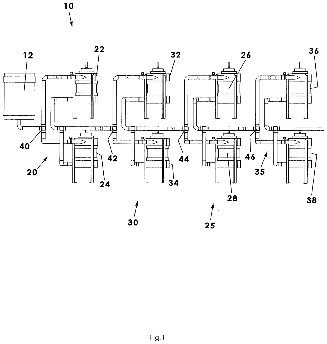
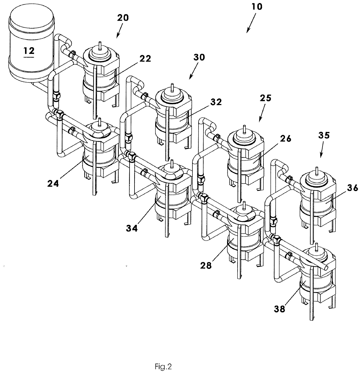
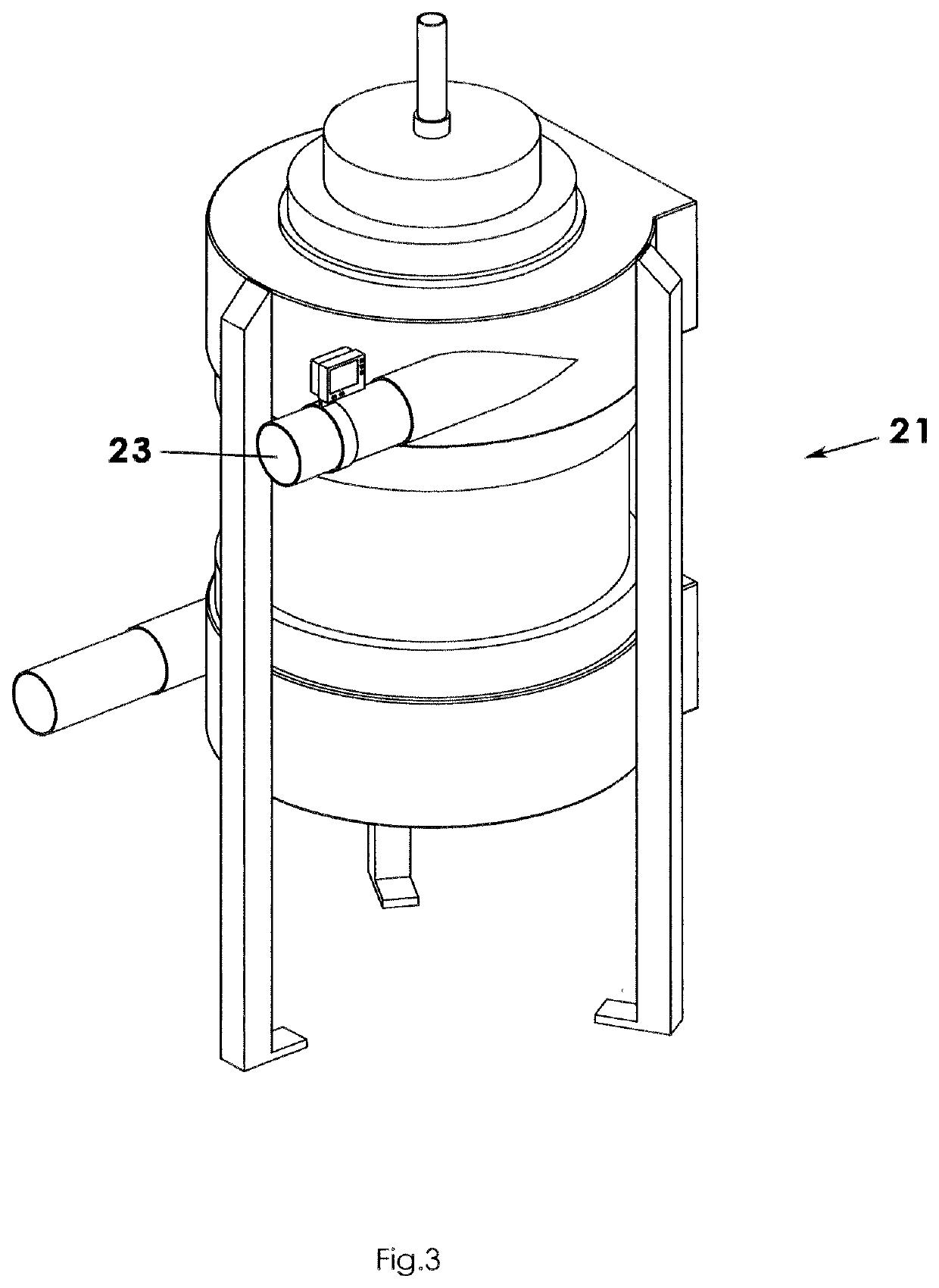
[0023]A continuous resin regeneration system according to a preferred embodiment of the present invention will now be described with reference to FIGS. 1 to 4 of the accompanying drawings. The continuous resin regeneration system 10 includes a first anion column set 20, a first cation column set 30, a second anion column set 25, and a second cation column set 35. It is understood that each column set includes at least two filtration columns and, in some applications, more than two.

[0024]For clarity of terminology in the present application, the first anion column set 20 includes a first anion column 22 notated in the drawings as A1a and a second anion column 24 notated in the drawings as A1b. Similarly, the first cation column set 30 includes the first cation column 32 notated in the drawings as C1a and a second cation column 34 notated in the drawings as C1b. Then, the second anion column set 25 includes a first anion column 26 notated in the drawings as A2a and a second anion colu...


PUM

PropertyMeasurementUnit
pHaaaaaaaaaa
oxidation reduction potentialaaaaaaaaaa
flow rateaaaaaaaaaa

Abstract

A continuous resin regeneration system includes a process by which resin in need of being recharged is continuously recharged and cleaned with a plurality of two-set filtration columns so that resin regeneration and the flow of influent is continuous and interrupted. Downstream filtration columns also undergo this cycling but at slower and related rates as the first column with the dirtiest water will naturally degrade resin faster than the downstream columns. Contaminated influent is cleaned by the continuously recharged resin in multiple column sets. The degree of cleaning of earlier filtration columns affects the resin flow rate of later filtration columns.

Description

REFERENCE TO RELATED APPLICATIONS[0001]This application claims the benefit of provisional patent application 62 / 872,093 filed Jul. 9, 2019 and titled Continuous Resin Regeneration System, which claims the priority of non-provisional patent application Ser. No. 16 / 179,310 filed Nov. 2, 2018 and titled Continuous Resin Regeneration System which claims the benefit of provisional patent application U.S. Ser. No. 62 / 622,248 filed Jan. 26, 2018 titled Continuous Resin Regeneration System all of which are incorporated in their entirety herein by reference.BACKGROUND OF THE INVENTION[0002]This invention relates to resin regeneration systems and, more particularly, to a multi-column continuous resin regeneration system in which influent water in need of cleaning or filtration is flowed through filtration columns of resin so long as the resin within a first column is not degraded beyond a predetermined amount and, if so, into a second column of like resin type having sufficiently charged resi...

Claims


Application Information

Patent Timeline
Patent Type & Authority Applications(United States)
IPC IPC(8): B01J49/85B01J49/08B01J49/70B01J47/028B01J41/04B01J41/12B01J39/04B01J39/18C02F1/42C02F1/00B01D15/36B01D15/20
CPCB01J49/85C02F2209/40B01J49/70B01J47/028B01J41/04B01J41/12B01J39/04B01J39/18C02F1/42C02F1/008B01D15/362B01D15/363B01D15/203C02F2001/422C02F2001/425C02F2303/16C02F2209/06C02F2209/10C02F2209/04B01J49/08B01J39/07B01J41/07B01J47/026
Inventor VANIER, JAYPOOL, RUSSELL D.
Owner VANIER JAY
Why Eureka
Try Eureka