Power storage element

a technology of power storage element and separator, which is applied in the direction of wound/folded electrode electrodes, sustainable manufacturing/processing, batteries, etc., can solve the problems of difficult separation of separators larger than electrode plates, and the power generation performance of the electrode winding body is not restrained, so as to facilitate operation and improve the liquid retention at the upper part of the electrode winding body.

Pending Publication Date: 2020-12-24
TOYOTA JIDOSHA KK
View PDF1 Cites 0 Cited by
  • Summary
  • Abstract
  • Description
  • Claims
  • Application Information

AI Technical Summary

Benefits of technology

[0010]In the power storage element according to the above aspect, the electrode winding body may be a flat winding body having a flat portion and two turning portions, and at least one of the insulating members may be disposed on an upper turning portion of the two turning portions in a use state of the power storage element. In the electrode winding body, there is a gap adjacent to an end of the second electrode plate on the winding end side (the third end or the fourth end). In the above aspect, the gap is large because the insulating member is interposed between the two electrode plates. This gap can function as an electrolyte solution reservoir. When the electrode winding body is of a flat type, according to the above aspect, liquid retainability at the upper part of the electrode winding body can be improved.
[0011]In the power storage element according to the above aspect, the insulating member may be a resin tape, such that one surface of the insulating member is an adhesive surface. The insulating member may be provided on front and back surfaces of the second electrode plate at the third end and the fourth end, with the adhesive surface facing the second electrode plate and a part of the insulating member disposed so as to protrude outward from the second electrode plate in the longitudinal direction. With this configuration, the position of the insulating member is stabilized before the winding, which facilitates the operation of winding the first electrode plate and the second electrode plate into an electrode winding body.
[0012]According to this configuration, there is provided a power storage element that uses a separator-integrated electrode plate and suppresses a short circuit between positive and negative electrode plates in an electrode winding body, particularly at a third end and a fourth end of the electrode plate.

Problems solved by technology

However, the technique described in JP 2018-060631 A described above has the following problems.
The reason is that, unlike the case of the film separator, it is difficult to form a separator larger than the electrode plates with the separator-integrated electrode plate in size.
Since the insulating member is not provided in the region between the third end and the fourth end, the power generation performance of the electrode winding body is not restrained.

Method used


Image

  • Power storage element
  • Power storage element
  • Power storage element

Examples


Embodiment Construction

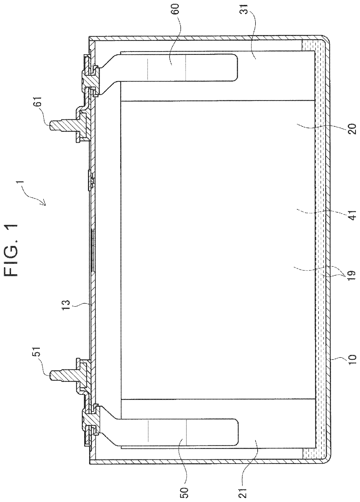
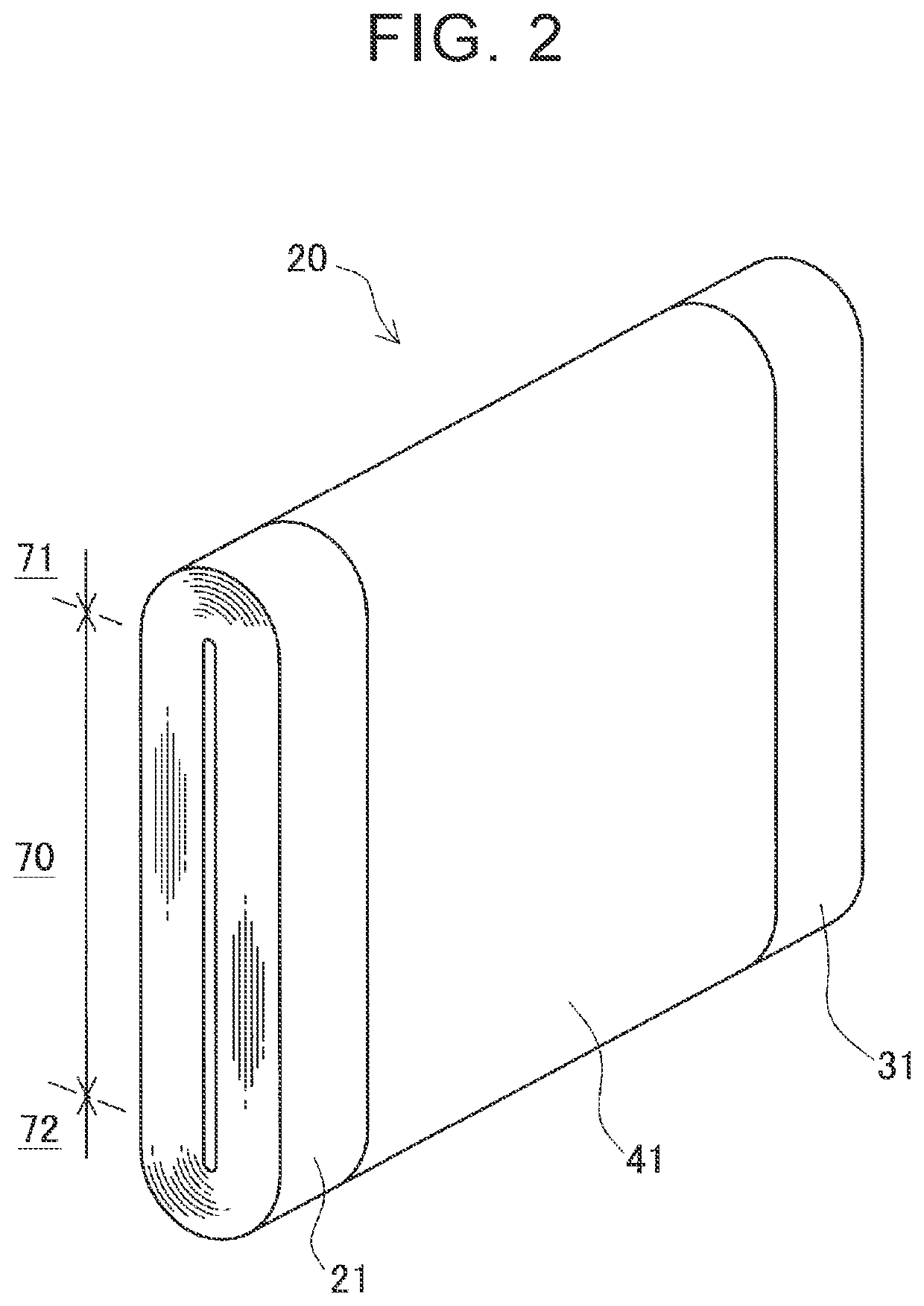
[0025]Hereinafter, an embodiment implementing a power storage device of the disclosure will be described in detail with reference to the accompanying drawings. In the embodiment, the disclosure is applied to a battery 1 shown in FIG. 1. The battery 1 shown in FIG. 1 has a flat rectangular battery case 10 in which an electrode winding body 20 is housed. The electrode winding body 20 has a power generating portion 41 disposed at the center of the electrode winding body 20, and a positive electrode connecting portion 21 disposed on one side of the power generating portion 41 and a negative electrode connecting portion 31 disposed on the other side thereof. The battery case 10 stores an electrolyte solution 19 in addition to the electrode winding body 20. A part of the stored electrolyte solution 19 is impregnated in the electrode winding body 20. A positive electrode terminal 51 and a negative electrode terminal 61 are provided on a lid portion 13 of the battery case 10. Inside the bat...


PUM

PropertyMeasurementUnit
sizeaaaaaaaaaa
widthaaaaaaaaaa
widthaaaaaaaaaa

Abstract

A protruding portion of a current collecting foil is provided at one end in a width direction over an entire length in a longitudinal direction. A first end of a positive electrode plate, which is located on a side on which the protruding portion is provided, is located outward of a second end in the width direction, the second end being an end of a positive electrode active material layer in the width direction located adjacent to the protruding portion. An insulating tape is interposed between a positive electrode plate and the negative electrode plate. Regarding a size and a position of the insulating tape, the insulating tape is provided in a region including the second end and the first end in the width direction, and the insulating tape is provided in a region including longitudinal ends of the positive electrode plate in the longitudinal direction.

Description

INCORPORATION BY REFERENCE[0001]The disclosure of Japanese Patent Application No. 2019-113980 filed on Jun. 19, 2019 including the specification, drawings and abstract is incorporated herein by reference in its entirety.BACKGROUND1. Technical Field[0002]The disclosure relates to a power storage element having an electrode winding body formed by winding belt-shaped positive and negative electrode plates. More specifically, the disclosure relates to a power storage element that uses a separator-integrated electrode plate in which a separator is integrated with one of the electrode plates to restrain a short circuit between the electrode plates.2. Description of Related Art[0003]Examples of the power storage element that uses a separator-integrated electrode plate include those described in Japanese Unexamined Patent Application Publication No. 2018-060631 (JP 2018-060631 A). In a battery described in JP 2018-060631 A, the separator-integrated electrode plate is used as the negative el...

Claims


Application Information

Patent Timeline
Patent Type & Authority Applications(United States)
IPC IPC(8): H01M10/0587
CPCH01M10/0587H01M10/0583H01M4/13H01M4/667H01M2004/028H01M2200/30H01M10/0431H01M50/474H01M50/486Y02E60/10Y02P70/50H01M10/4235H01M50/46H01M50/463C09J2203/33
Inventor SAKURAI, TAKAHIRO
Owner TOYOTA JIDOSHA KK
Why Eureka
Try Eureka