Sonar unit

Pending Publication Date: 2020-12-17
WHETRON ELECTRONICS (SUZHOU) CO LTD +1
View PDF1 Cites 0 Cited by
  • Summary
  • Abstract
  • Description
  • Claims
  • Application Information

AI Technical Summary

Benefits of technology

This patent describes a structure that protects electronic components from noise outside a circuit substrate. A shield unit is placed on the front surface or back surface of the circuit substrate, with a plate portion that overlaps the electronic components. This shield unit blocks the noise that may affect the components. When the shield unit is placed on the back surface, the operator can approach it through a window portion to perform soldering or other operations. The shield unit ensures that the electronic components are protected from noise. The spaces on the opposite surfaces of the shield unit communicate with each other through the window portion, which allows for easy removal of air bubbles during sealing. Overall, this structure allows for relaxed assembly restrictions and improves the reliability of the electronic components.

Problems solved by technology

Thus, the reworking property is low.

Method used


Image

  • Sonar unit
  • Sonar unit
  • Sonar unit

Examples


Embodiment Construction

[0021]A sonar unit according to an embodiment of the present disclosure will be described with reference to the drawings.

[0022]Schematic Configuration

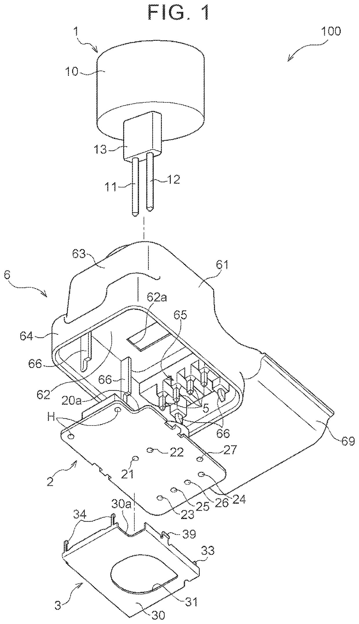
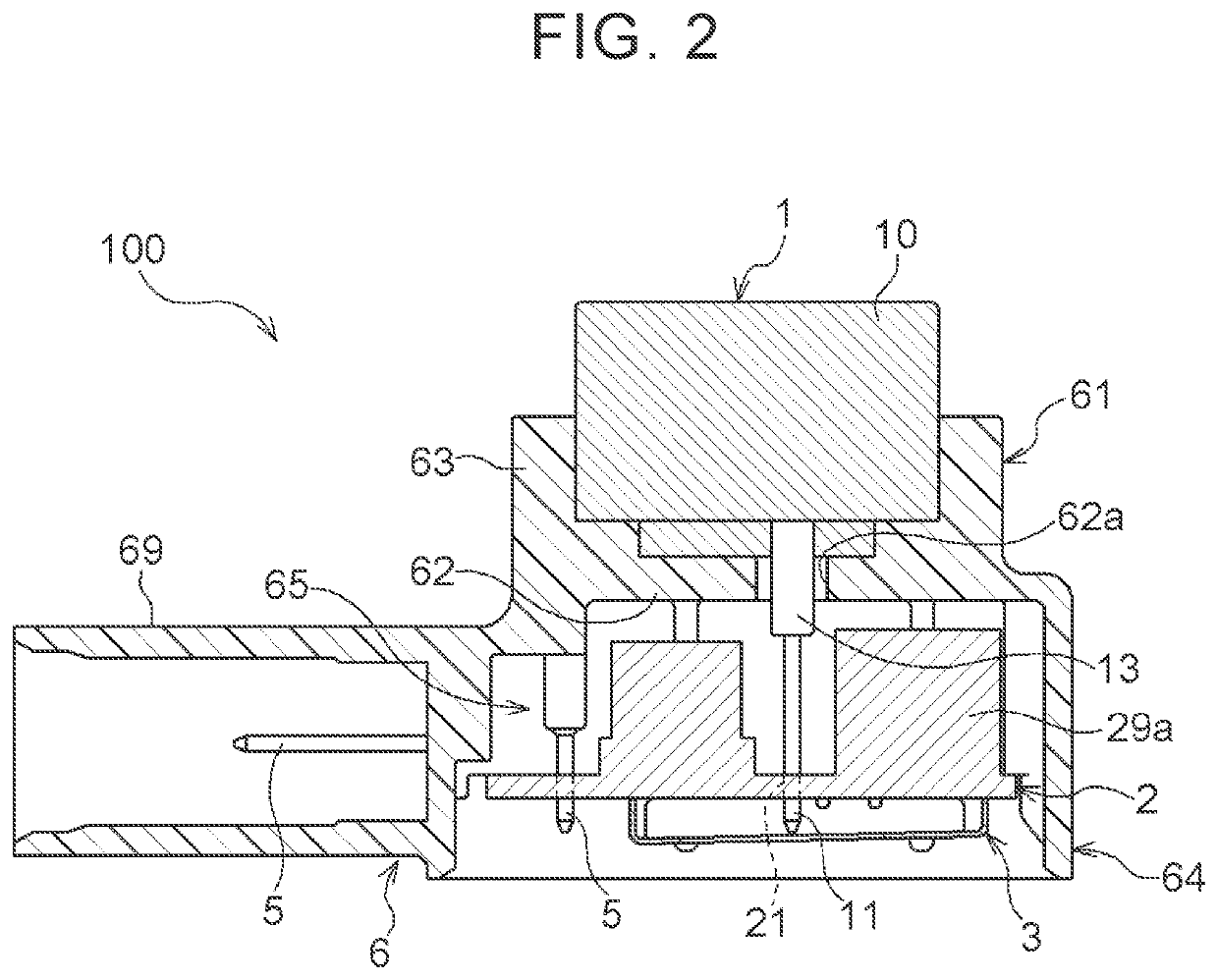
[0023]FIG. 1 illustrates an exploded perspective view of a sonar unit (hereinafter referred to as a sonar 100) used as an in-vehicle distance sensor for collision prevention or the like, for example.

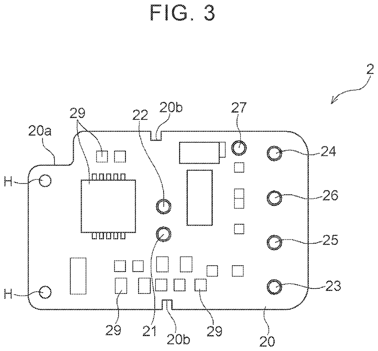
[0024]The sonar 100 includes a circuit substrate (hereinafter referred to as a substrate 2) on which a transducer 1 including a piezoelectric element (not shown) or the like configured to transmit and receive ultrasonic waves is provided, a shield unit (hereinafter referred to as a shield 3) including a plate portion 30 covering the substrate 2, an input-output pin 5 electrically connected to the substrate 2 and serving as an interface for input and output of the sonar 100, and a housing 6 in which these members are accommodated. The input-output pin 5 includes four terminal pins, for example. The four terminal pins include two power pins a...


PUM


Abstract

A sonar unit includes: a circuit substrate on which a transducer, electronic components constituting a circuit configured to drive the transducer, and an input-output terminal for the circuit are mounted; and a shield unit. The shield unit includes a plate portion at a position where the plate portion overlaps at least a part of the electronic components when the shield unit is viewed in a thickness direction of the rectangular circuit substrate. The shield unit includes a window portion provided as a through-hole or a notch. The window portion is placed at a position close to the input-output terminal in a longitudinal direction of the rectangular circuit substrate when the window portion is viewed in the thickness direction of the rectangular circuit substrate.

Description

CROSS-REFERENCE TO RELATED APPLICATION[0001]This application claims priority to Japanese Patent Application No. 2019-111970 filed on Jun. 17, 2019, incorporated herein by reference in its entirety.BACKGROUND1. Technical Field[0002]The present disclosure relates to a sonar unit.2. Description of Related Art[0003]In a circuit substrate for a sensor unit or the like that is requested to perform an electrical process on a weak analogue signal, an influence of static electricity or an electromagnetic wave that mixes from outside is relatively large. In such a case, a shield unit configured to protect the circuit substrate from the electromagnetic wave or the like is used.[0004]Japanese Unexamined Patent Application Publication No. 2005-159144 (JP 2005-159144 A) describes a shield case (corresponding to a shield unit in the present application) in which easiness in attachment to a circuit substrate provided in an electronic device and a reworking property are improved. JP 2005-159144 A po...

Claims


Application Information

Patent Timeline
IPC IPC(8): G01S15/08G01S15/931G01S7/521
CPCB60R16/0231G01S7/521G01S15/931G01S15/08
Inventor SUMI, CHIAKINAKAMURA, TAKAAKINAGAI, TOSHIHITOHONG, GAOYANG
Owner WHETRON ELECTRONICS (SUZHOU) CO LTD
Why Eureka
Try Eureka