
Electrodeless plasma lamp

a technology of plasma lamps and plasma lamps, which is applied in the direction of electric discharge lamps, gas discharge lamps details, electrical equipment, etc., can solve the problems of limited lifetime, impede widespread use of such devices, and the electromechanical characteristics of these types of lamps are typically deteriorated, so as to maximise the transmissibility of light through the beam and reduce the effect of emission

Inactive Publication Date: 2020-12-10
TOPANGA ASIA LTD
View PDF0 Cites 0 Cited by
  • Summary
  • Abstract
  • Description
  • Claims
  • Application Information

AI Technical Summary

Benefits of technology

The patent describes an electromagnetic confinement member for a plasma lamp that reduces the emission of electromagnetic waves. The confinement member includes a plurality of apertures that are sized to maximize the light emitted and reduce the size of the aperture. The apertures can be formed using photolithography to improve light transmissibility. This configuration can enhance the performance of electrodeless plasma lamps and help to improve the overall quality of light emission.

Problems solved by technology

However, the electrodes of these types of plasma lamps typically deteriorate during prolonged use and therefore have a limited lifetime.
However, in such arrangements electromagnetic compatibility (EMC) issues caused by residual electric field leaking around the bulb and to the surrounding area remain problematic and impede widespread usage of such devices.

Method used


Image

  • Electrodeless plasma lamp
  • Electrodeless plasma lamp
  • Electrodeless plasma lamp

Examples


Embodiment Construction

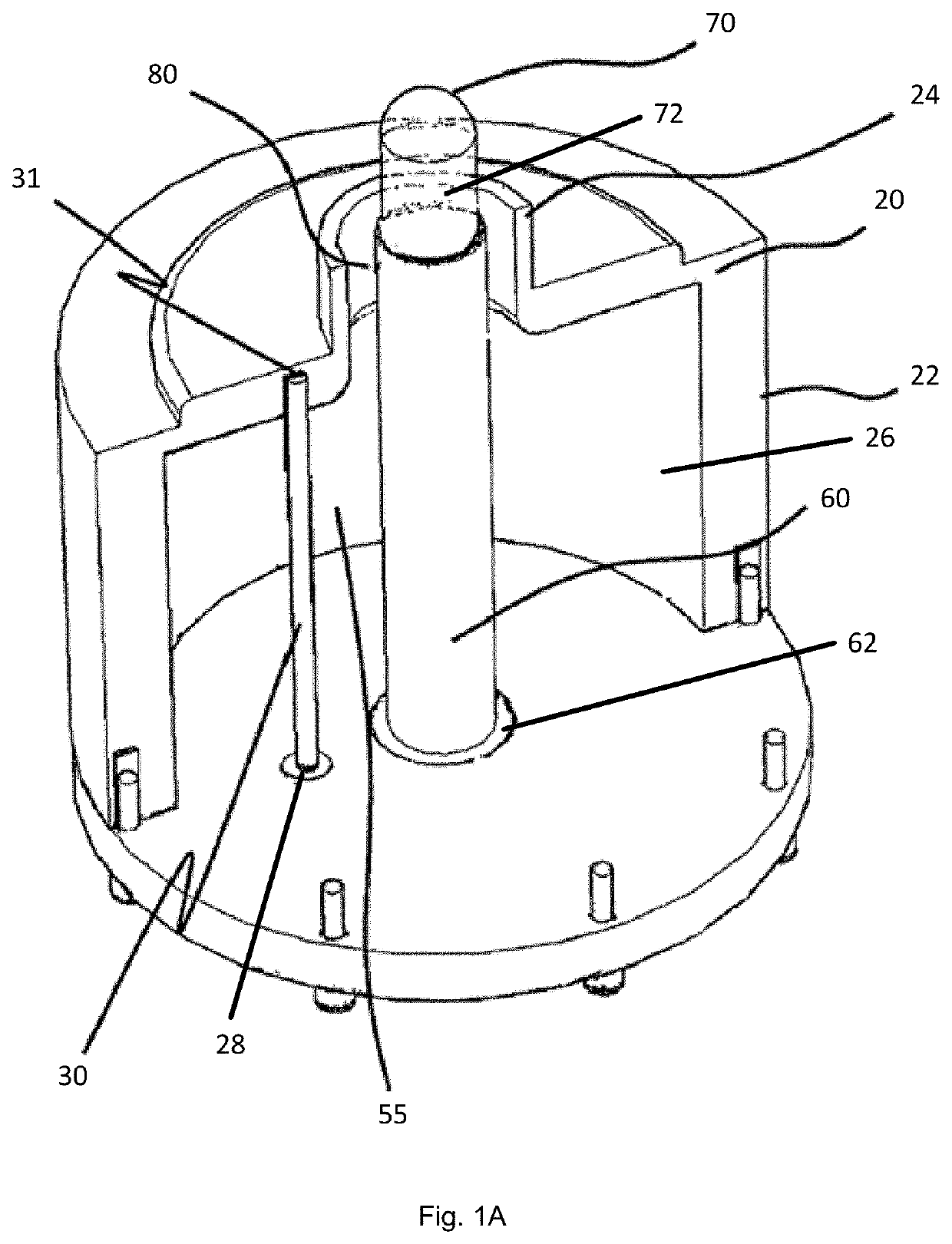
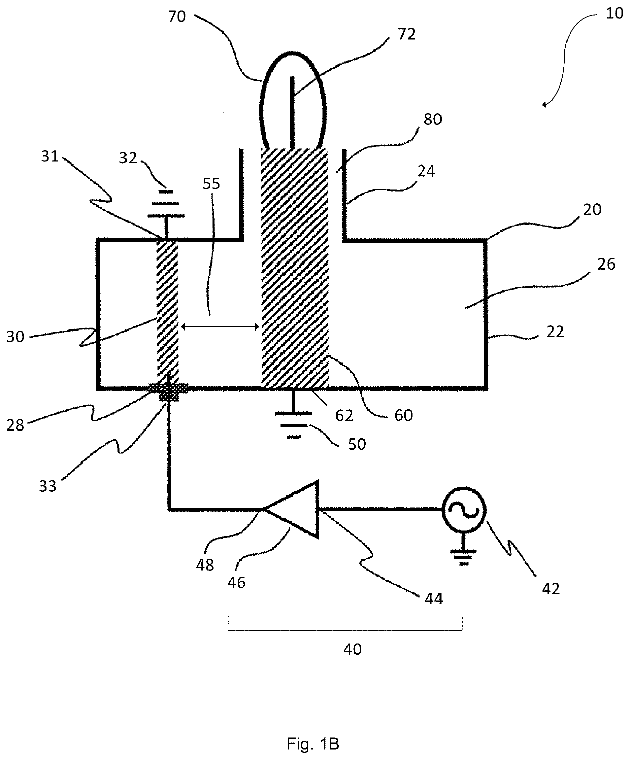
[0031]FIGS. 1A and 1B depict simplified views of an exemplary embodiment of a prior art electrodeless plasma lamp.

[0032]As depicted, the lamp 10 has a lamp body or housing 20 which has a broad bottom section 22 having a large diameter and a narrower top section 24. The lamp body is filled with air 26 or other gases such as nitrogen or fluids, or alternatively may be a vacuum. The surface of the housing is conductive; which may be either an inherent property of the material of the housing 20 or result from the application of a conductive veneer.

[0033]An input coupling element 30 is connected with the upper surface 31 of the lamp body 20 (which would be appreciated to be at ground potential 32). The other end of the input coupling element is connected to an RF connector 33 via an opening 28 in the lamp body 20. It would be appreciated that the input coupling element 30 may be solid or hollow conductor; or a dielectric material with an electrically conductive coating.

[0034]The RF sourc...


PUM


Abstract

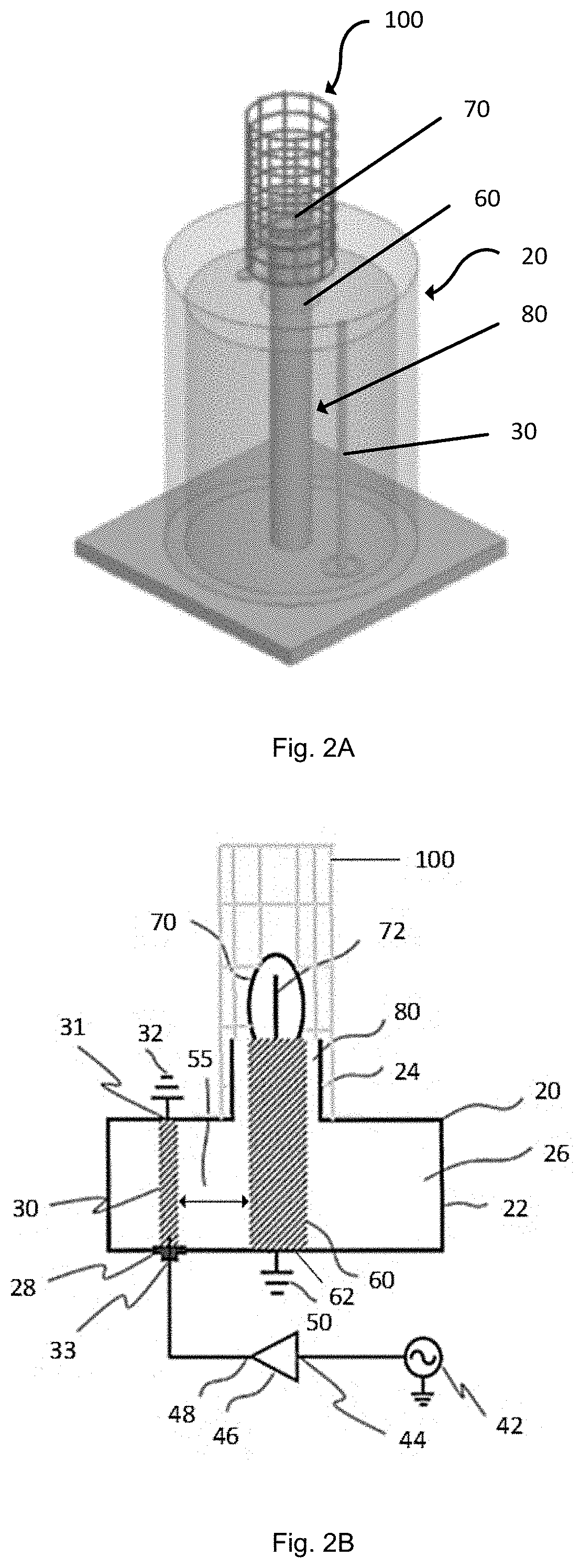
There is provided an electrodeless plasma lamp and confinement member for an electrodeless plasma lamp. The lamp comprises a lamp body with an input coupling element, with one end coupled to an RF source and the other end coupled to a first ground potential. An output coupling element is received substantially within the lamp body and spaced apart from the input coupling element and from the top of the lamp body, wherein one end of the output coupling element is coupled to a second ground potential and the other end of the output coupling element at the top of the lamp body is coupled to a gas filled vessel. An electromagnetic confinement member extends away from the lamp body and surrounds it for reducing emission of electromagnetic waves below a predetermined threshold frequency, and includes a plurality of apertures formed therein.

Description

FIELD[0001]The present disclosure is directed to electrodeless plasma lamp, especially an electrodeless lamp with high intensity discharge.BACKGROUND[0002]Plasma lamps provide extremely bright, broad spectrum light, and are useful in many applications, especially to provide general illumination of large areas including stadiums, parking lots etc; as well as in high ceiling areas such as industrial buildings where the light source is separated a long way from where it is needed.[0003]In traditional plasma lamps, plasma is generated from a mixture of gas and trace substances by using a high current passed between closely-contacting electrodes. However, the electrodes of these types of plasma lamps typically deteriorate during prolonged use and therefore have a limited lifetime.[0004]Electrodeless plasma lamps have also been developed, with light energy generated by coupling radio frequency (RF) energy from an RF driver or source to a gas-filled vessel (bulb). Typically the RF source i...

Claims


Application Information

Patent Timeline
Patent Type & Authority Applications(United States)
IPC IPC(8): H01J65/04H01J61/04
CPCH01J65/042H01J61/04H01J61/30H01J65/06H01J61/10
Inventor LAM, WING YIULEE, YUEN FATLAU, EDDIE KOON CHUNG
Owner TOPANGA ASIA LTD
Learn More