Eureka AIR delivers breakthrough ideas for toughest innovation challenges, trusted by R&D personnel around the world.

Crowbar device and multistage crowbar apparatus

a multi-stage, crowbar technology, applied in the direction of electrical devices, switches operated by abnormal voltage/current products/phase angles, electrical apparatus, etc., can solve the problems of permanent overvoltage, small losses, and overvoltage on the high-voltage bushing

Active Publication Date: 2020-11-19
HITACHI ENERGY SWITZERLAND AG
View PDF0 Cites 0 Cited by
  • Summary
  • Abstract
  • Description
  • Claims
  • Application Information

AI Technical Summary

Benefits of technology

The patent describes a new device for protecting AC voltage sources from overvoltage events. The device uses a unique technique called crowbar protection, which is more efficient and has lower losses compared to traditional clamping devices. The device can be stacked to multiple stages to increase its threshold voltage, providing more flexibility and safety. Additionally, the device allows for continuous safe operation even in case of failure. Overall, the device provides a simple and effective solution for overvoltage protection.

Problems solved by technology

Overvoltages on the high-voltage bushing may occur e. g. due to transients in the AC voltage supply, or due to an internal failure of the high-voltage divider.
A transient in the AC voltage supply occurs for a relatively short period of time, whereas an internal failure of the high-voltage divider may lead to a permanent overvoltage, which has to be coped with.
Here, the discharge losses are small, but the conduction losses are significant.
However, these types of conventional crowbar circuits suffer from the high conduction losses in the case of a permanent overvoltage failure, which may lead to the destruction of the protective device of the crowbar circuit.
In medium to high impedance AC voltage source applications, the impedance of the AC voltage source is too high to keep the above-mentioned types of devices in a conducting state.
Such a multiple triggering may lead to high discharge losses which are in the same order of magnitude as the use of e. g. a surge arrester or a varistor.
The conventional AC devices are not suitable for a prolonged power surge clamping, such as those occurring in a permanent failure state of a high impedance voltage source.
The conventional DC devices cannot be applied to alternating currents, and rely upon an external failure signal to trigger a power surge clamping.
With respect to the devices that reduce the voltage across the crowbar circuit near zero, high impedance voltage sources may not have the ability to supply a necessary holding current for these devices, which leads to an unwanted turn-off of the protective device and a recharging operation of the overvoltage condition at the voltage source.
Subsequent triggering leads to high power losses in the protective device, which may lead to its destruction.

Method used


Image

  • Crowbar device and multistage crowbar apparatus
  • Crowbar device and multistage crowbar apparatus
  • Crowbar device and multistage crowbar apparatus

Examples


Embodiment Construction

[0037]The embodiments described below with reference to the accompanying drawings are illustrative in every aspect and may be combined with one another and / or modified and / or abbreviated and / or omitted as appropriate.

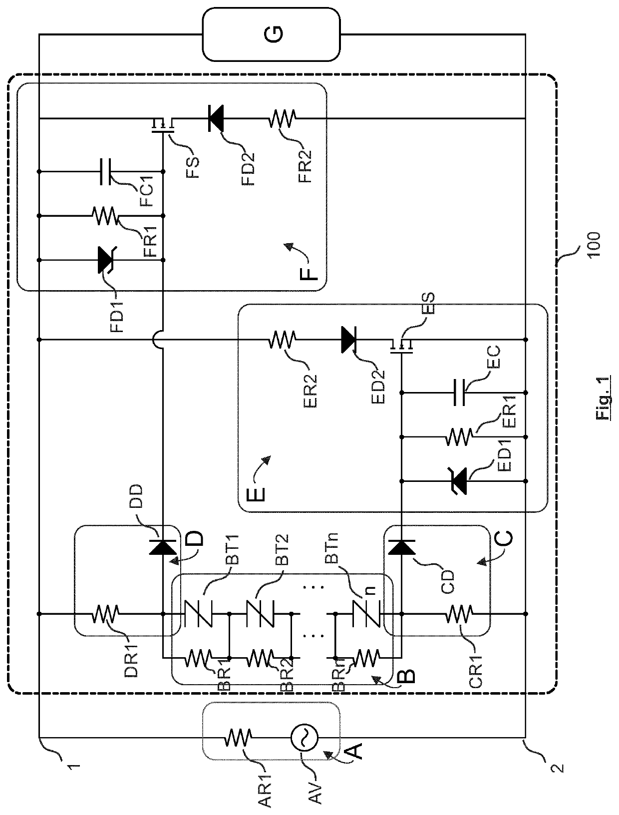
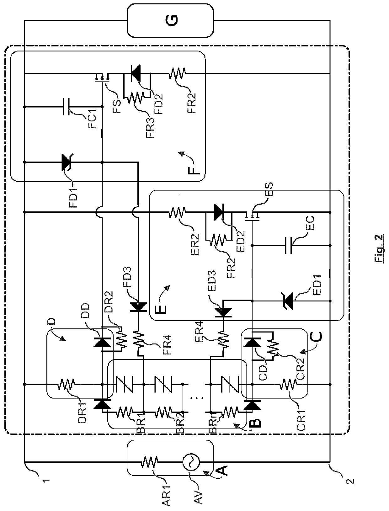
[0038]FIGS. 1 and 2 each illustrate a circuit diagram showing an exemplary configuration of a crowbar device according to an embodiment of the disclosure.

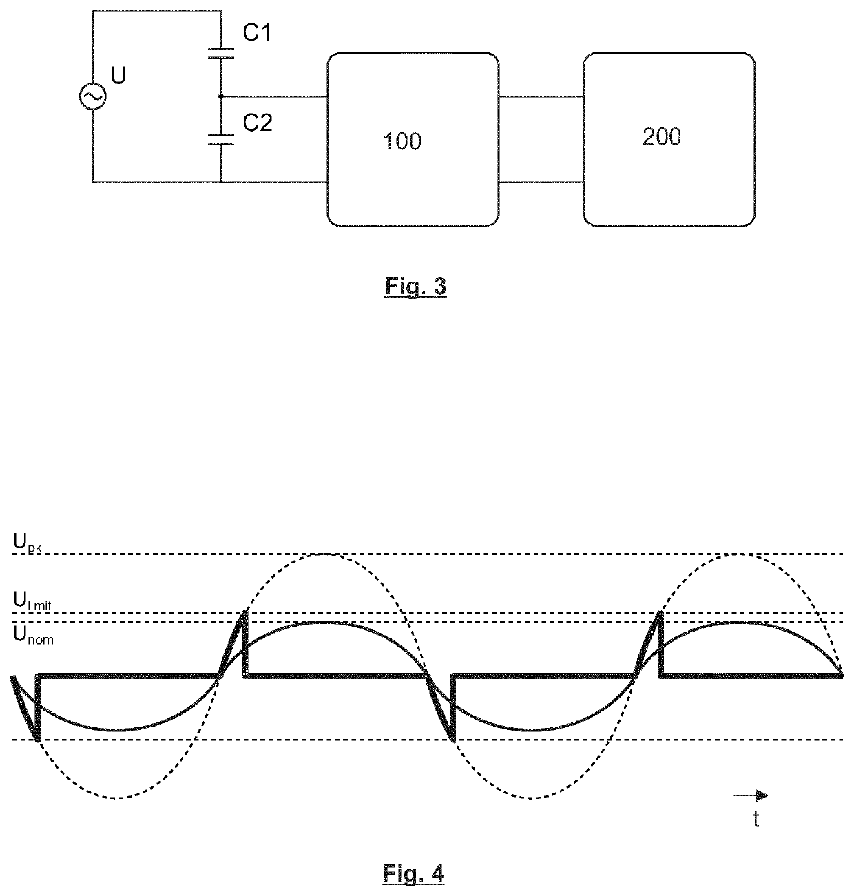
[0039]FIG. 3 shows an exemplary configuration of a high impedance voltage source U having a crowbar device 100 and an equipment 200 connected thereto. The voltage source U corresponds to the voltage source AV in FIGS. 1 and 2. In FIG. 3, the capacitors C1 and C2 illustrate the high impedance properties of the voltage source U. For example, the voltage source U has a capacitance C2 between signal and ground. The overvoltage protection circuit, or crowbar device 100, is connected between the terminals of capacitance C2. In case of operation of the crowbar device, it discharges the capacitance C2 between signal and ground...


PUM


Abstract

A crowbar device has a first terminal and a second terminal, the terminals being connectible to a medium to high impedance AC voltage source including a trigger circuit configured to output a trigger signal responsive to exceeding a threshold voltage across at least one trigger element of the trigger circuit; a positive-side signaling circuit and a negative-side signaling circuit configured to output a positive or a negative clamping signal, respectively, according to a positive-voltage or a negative-voltage signal, respectively, input from the trigger circuit; and a positive-side overvoltage clamping circuit and a negative-side overvoltage clamping circuit configured to control their respective semiconductor element to be in a conducting state, when the clamping signal from the corresponding signaling circuit is present, and configured to control their semiconductor element to be in a non-conducting state, when the corresponding clamping signal has not been present for a predetermined time period.

Description

TECHNICAL FIELD[0001]The present disclosure relates to a crowbar device and a multistage crowbar apparatus connectible to a medium to high impedance AC voltage source.[0002]Crowbar circuits are typically used to protect a technical equipment connected to a source of a power supply from damages due to an overvoltage, such as an overvoltage stemming from transient effects like switching operations in a network. A type of an equipment connected to a high-voltage power supply part, such as an AC high-voltage bushing, is a measurement circuit. For example, in an AC high-voltage bushing a high-voltage divider is used for connecting such a measurement circuit. In a high-voltage bushing, the high-voltage divider may comprise, for example, an equipotential surface of a bushing component arranged in an outer layer of the bushing, such as the second outermost layer of the bushing.[0003]The high-voltage divider in such an exemplary kind of application makes the voltage source sensed by the meas...

Claims


Application Information

Patent Timeline
IPC IPC(8): H02H9/04H02H9/06
CPCH02H9/04H02H9/06H02H9/041H02H3/20H02H3/22H01H83/18H01H47/00H02H3/00
Inventor SJÖKVIST, HANSHÜNENMÖRDER, SVENEPPRECHT, LUKASSCHUETTE, THOMASSTUDER, MARTIN
Owner HITACHI ENERGY SWITZERLAND AG
Why Eureka
Eureka Blog
Learn More