
Method and apparatus for increasing the efficiency of the cogeneration power plant by the heat pump principle utilization for increasing the coolant inlet temperature

a technology of heat pump and heat pump blade, which is applied in the direction of lighting and heating apparatus, sustainable buildings, heating types, etc., can solve the problems of poor cop of heat pump, and low heat transfer efficiency of heat pump, so as to improve cop, improve heat transfer efficiency, and reduce fluctuation

Inactive Publication Date: 2020-10-15
UNIVERSITY OF MARIBOR
View PDF0 Cites 4 Cited by
  • Summary
  • Abstract
  • Description
  • Claims
  • Application Information

AI Technical Summary

Benefits of technology

The invention describes a heat pump system that improves the efficiency of power conversion by heating the cooling fluid downstream of the heat consumer (e.g. in the return line). This reduces the temperature at the return line compared to the supply line, allowing the heat pump to heat the fluid to lower temperatures. The control parameter is the temperature of the cooling fluid at the entry of the cooling system for the primary heat source. The heat pump uses low-temperature heat available from the ambient and converts it into higher-temperature heat, which is then introduced into the cooling system for the primary heat source. This results in a higher overall power conversion efficiency. The patent text also explains that the heat pump has an outlet that is connected to the cooling system of the primary heat source, which further improves the efficiency of the system.

Problems solved by technology

The solution according to the US20100003552 discloses a fuel cell with incorporated heat pump for fuel cell waste heat source (i.e. exhaust gas) utilization, where the key defect of the proposed solution is that the waste heat generated by the fuel cell is used for heat pump principle utilization, hence the COP of the heat pump is due to high temperatures of the heat transfer medium relatively poor in comparison to herein disclosed solution.
According to the patents DE 10 2012 106894 and DE 39 12 113 the main disadvantage of disclosed solutions is that none of those does not disclose any hint to connect the evaporator and waste heat source recovery unit with closed loop circuit for direct waste heat utilization, as disclosed by herein explained solution.

Method used


Image

  • Method and apparatus for increasing the efficiency of the cogeneration power plant by the heat pump principle utilization for increasing the coolant inlet temperature
  • Method and apparatus for increasing the efficiency of the cogeneration power plant by the heat pump principle utilization for increasing the coolant inlet temperature
  • Method and apparatus for increasing the efficiency of the cogeneration power plant by the heat pump principle utilization for increasing the coolant inlet temperature

Examples


Embodiment Construction

ples

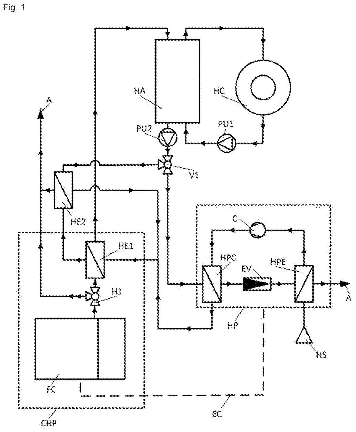
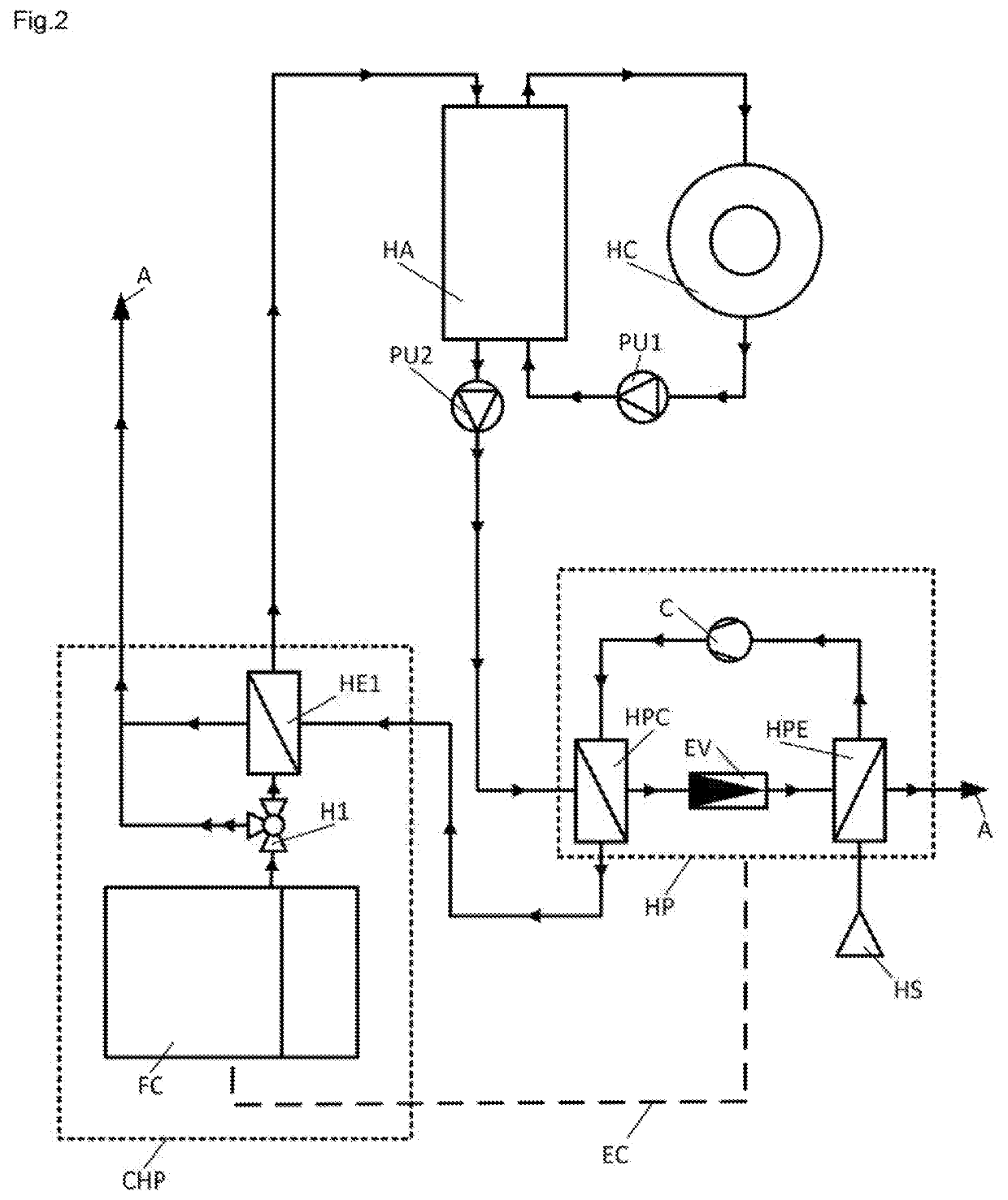
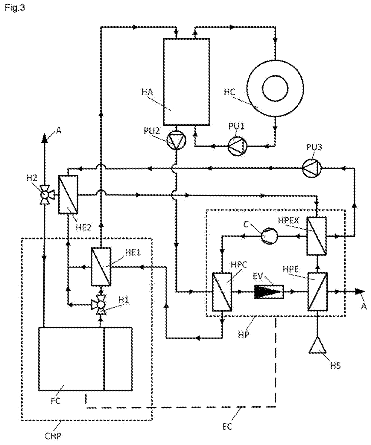
[0021]In preferential embodiment, the cogeneration of heat and power (CHP) assembly comprises at least one primary heat source (i.e. fuel cell (FC) or internal combustion engine (ICE)) with adapted heat exchangers (HE1, HE2) for waste heat (i.e. flue gas) recuperation, and at least one heat pump (HP) with adapted evaporator (HPE) for renewable energy source (HS) utilization. As can be read out from the FIG. 1 and FIG. 4, the waste heat of said primary heat source for the cogeneration of the heat and power (CHP) assembly is at least partially introduced into the heat distribution network by heat exchangers (HE1, HE2), wherein the high-temperature heat of the flue gas is introduced into the supply line of the heat distribution network by the first heat exchanger (HE1) (i.e. the temperature of the flue gas is reduced below 140° C.), and similarly, the second heat exchanger (HE2) is preferably adapted to utilize the residual, low-temperature heat, by reducing the temperature of the ...


PUM


Abstract

The method and apparatus for increasing the efficiency of a low-temperature or high temperature heating system, comprising a primary heat releasing unit (i.e. cogeneration unit with fuel cell (FC) or internal combustion engine (ICE)) for co-generation of the heat and power, and at least one secondary heat releasing unit (i.e. heat pump (HP)) for utilization of at least one of the available waste / renewable energy heat sources (HS) from the ambient (A), where the heat generated by said heat pump is preferably used for preheating the heat transfer medium in the return line of the closed loop heating system, wherein a primary heat releasing unit is used to heat the heat transfer medium to the required temperature level of the heat distribution network. The apparatus according to the invention may comprise one or more heat pumps (HP) of the same or different types, and one or more primary heat releasing units in serial, parallel or cascade connection circuits.

Description

TECHNICAL FIELD[0001]The main object of the invention relates to the methods and apparatus for increasing the heating / cooling power of the cogeneration and / or tri-generation power plants by employing the heat pump principle for exploiting the available renewable low temperature heat sources (i.e. from ambient / ground), wherein the heat generated by the heat pump principle utilization is preferably used for preheating, more particularly, for increasing the temperature of the heat transfer medium in the return line of the heat distribution network (i.e. district heating).BACKGROUND ART[0002]Heat pumps that have been used in prior art to enhance the heating power of combined heat and power systems by utilizing the waste heat recovery and renewable heat sources exists in a number of designs. The solution according to the US20100003552 discloses a fuel cell with incorporated heat pump for fuel cell waste heat source (i.e. exhaust gas) utilization, where the key defect of the proposed solu...

Claims


Application Information

Patent Timeline
Patent Type & Authority Applications(United States)
IPC IPC(8): F24D19/10F24T50/00F24D3/18
CPCF24D19/1048F24T50/00F24D19/1039F24D2200/30F24D19/1066F24D2200/19F24D3/18F24D2200/26F24D2200/11F24D2200/12Y02B10/40Y02B10/70Y02B30/12Y02E10/10F24D18/00
Inventor GORICANEC, DARKO
Owner UNIVERSITY OF MARIBOR
Learn More