
Electronic device and method for communicating with external device through power source line

a technology of electrical devices and power supply lines, applied in the direction of charging attachments/accumulators, safety/protection circuits, instruments, etc., can solve the problems of complex structure and increase in part unit prices, and achieve the effect of simple structure and lowering a part unit pri

Active Publication Date: 2020-10-08
SAMSUNG ELECTRONICS CO LTD
View PDF0 Cites 15 Cited by
  • Summary
  • Abstract
  • Description
  • Claims
  • Application Information

AI Technical Summary

Benefits of technology

The patent text describes an electronic device with a simple structure that reduces the number of lines, pins, and connectors needed for power and data communication, which lowers the cost of the device. The technical effect is a more efficient and cost-effective electronic device.

Problems solved by technology

Accordingly, a structure is complicated and a part unit price may rise.

Method used


Image

  • Electronic device and method for communicating with external device through power source line
  • Electronic device and method for communicating with external device through power source line
  • Electronic device and method for communicating with external device through power source line

Examples


Embodiment Construction

[0028]FIGS. 1 through 12, discussed below, and the various embodiments used to describe the principles of the present disclosure in this patent document are by way of illustration only and should not be construed in any way to limit the scope of the disclosure. Those skilled in the art will understand that the principles of the present disclosure may be implemented in any suitably arranged system or device.

[0029]Hereinafter, various example embodiments of the disclosure will be described in greater detail with reference to accompanying drawings.

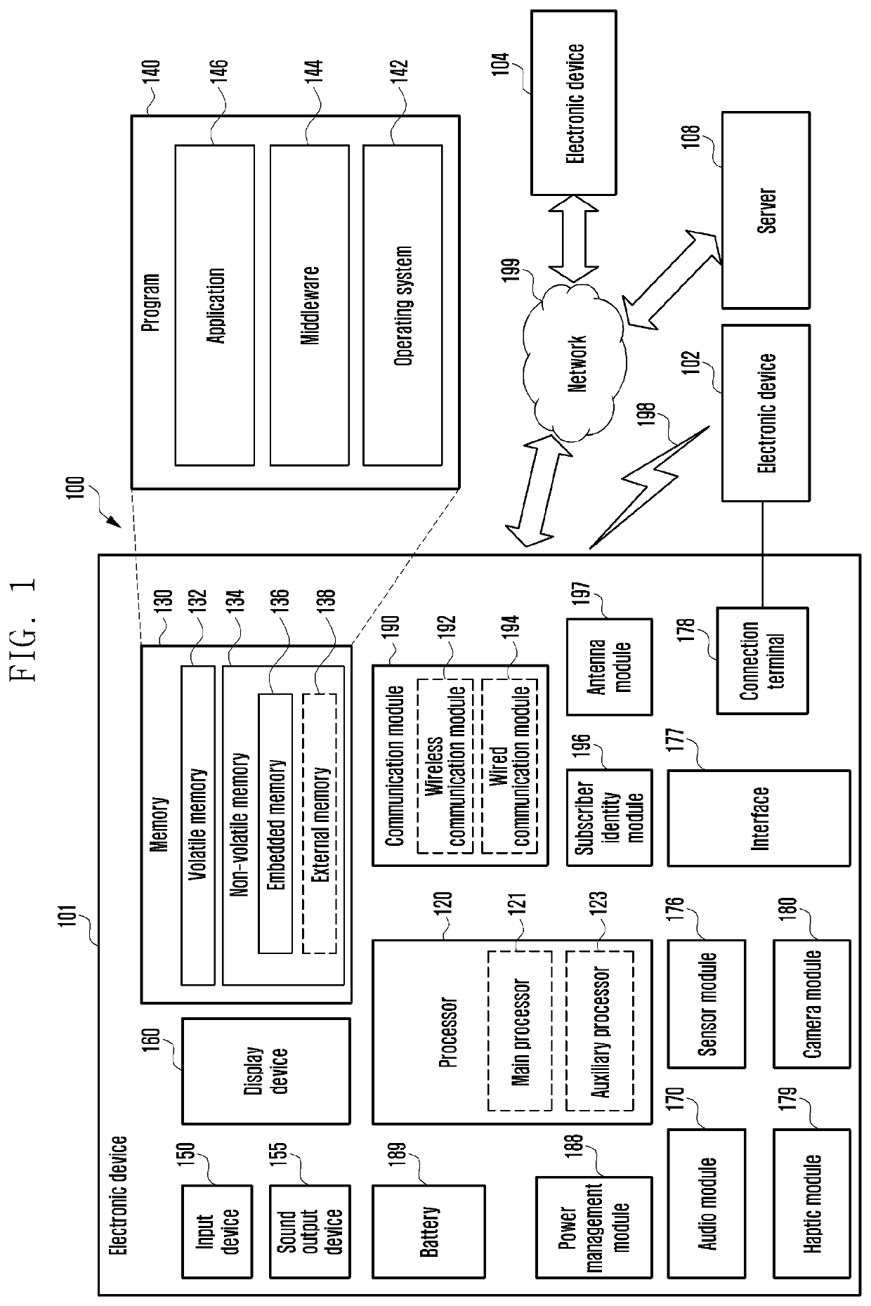
[0030]FIG. 1 is a block diagram illustrating an electronic device 101 in a network environment 100 according to various embodiments. Referring to FIG. 1, the electronic device 101 in the network environment 100 may communicate with an electronic device 102 via a first network 198 (e.g., a short-range wireless communication network), or an electronic device 104 or a server 108 via a second network 199 (e.g., a long-range wireless communication...


PUM


Abstract

An electronic device includes a battery, a charging integrated circuit (IC) configured to control a charging state of the battery, a connector pin for receiving power from an external device, the connector pin including a first connector pin for receiving a high potential voltage from the external device and a second connector pin for receiving a low potential voltage from the external device, a touch sensor, and a controller. The controller receives power from the external device through the connector pin based on the detection of the external device being connected to the connector pin, charges the battery using a high potential voltage, detects a user input through the touch sensor while the battery is charged, and stops the charging of the battery and outputs a current corresponding to state information of the electronic device through the first connector pin based on the detection of the given user input.

Description

CROSS-REFERENCE TO RELATED APPLICATION[0001]This application is based on and claims priority under 35 U.S.C. § 119 to Korean patent application number 10-2019-0039593, filed on Apr. 4, 2019, in the Korean Intellectual Property Office, the disclosure of which is incorporated by reference herein in its entirety.BACKGROUND1. Field[0002]The disclosure relates to an electronic device with which a cradle is also provided and to an electronic device and method capable of transmitting and receiving data through a power source pin of a cradle.2. Description of Related Art[0003]With the help of the electronic technology, various types of electronic devices are developed and supplied. Recently the supply of portable electronic devices having various functions, such as a smartphone, a tablet PC, a smart watch, or a smart earphone, is increased.[0004]The manufacturers of electronic devices provide a cradle for the charging of the battery of an electronic device or for data transmission and recep...

Claims


Application Information

Patent Timeline
IPC IPC(8): H02J7/00H04R1/10
CPCH04R2420/07H02J7/00034H02J7/0045H04R1/1025H02J7/0049H04R2420/09H02J7/0036A45C2011/001G06F3/017H02J7/00304
Inventor RHEE, DAESUNCHO, JONGHYUK
Owner SAMSUNG ELECTRONICS CO LTD
Learn More