
Process for ammonia production

a technology for ammonia production and ammonia, applied in the field of ammonia production, can solve the problems of high cost of recompression and large size of all synthesis loop equipment, low ammonia concentration equilibrium, and inability to compensate for the higher cost of the greater number of beds

Inactive Publication Date: 2020-10-08
CASALE SA
View PDF0 Cites 0 Cited by
  • Summary
  • Abstract
  • Description
  • Claims
  • Application Information

AI Technical Summary

Benefits of technology

The invention is a method for removing ammonia from a product gas using a solid adsorbent. The method includes two steps: an adsorptive step and a regeneration step. The adsorptive step removes ammonia from the gas using the solid adsorbent, resulting in a depleted gas and a loaded adsorbent. The regeneration step desorbs the ammonia from the adsorbent, resulting in an ammonia-containing gas. The invention provides an efficient way to remove ammonia from a gas stream, reducing the amount of catalyst required and minimizing the size of the catalyst bed. The method can be carried out in a fixed bed or a pseudo-isothermal bed. The main technical effects are a smaller amount of catalyst required, a smaller size of the catalyst bed, and improved kinetics of the reaction.

Problems solved by technology

However, for technical and economical limitations, the industrial ammonia production is carried out at temperature higher than 350° C. which ensures that the catalyst is active and at pressure lower than 200 bar, thus entailing a low equilibrium ammonia concentration.
The unfavourable equilibrium of the reaction limits the ammonia concentration achievable under practical conditions to about 20% mol or less, which corresponds to a conversion per pass lower than 30%.
In particular, a high conversion per pass reduces the amount of unconverted reactants that must be recycled back to the reactor(s); a large recycle stream is undesirable as it leads to high costs for recompression and large size of all synthesis loop equipment.
Although said configurations entail an increase of the conversion per pass, such increase is marginal and does not compensate for the higher costs required by the greater number of beds.
Even the use of larger catalyst volumes does not provide for a significant increase of the conversion per pass which is able to compensate for the higher costs of the larger equipment required.
However, none have been successfully applied in industrial ammonia production.
Such processes entail higher conversion per pass and higher reaction rates, but still have several drawbacks.
In fact, such higher conversion per pass entails extremely high temperatures, due to exothermic ammonia synthesis reaction.
At such high temperatures the ammonia synthesis catalyst will deteriorate.
Moreover, corrosive phenomena such as those from nitrogen and hydrogen attacks are more severe at higher temperatures.
Hence, pressure vessels may require costly materials (e.g. stainless steel or Inconel) to withstand these conditions and complicated mechanical designs may be required to protect the pressure vessels from high temperatures (e.g. flushing or cartridge insulations).
In addition, the aforementioned mixed beds containing both adsorbent and catalyst must withstand both the high temperature achieved by the reaction and the temperature / pressure cycles for the adsorbent regeneration, thus originating significant mechanical stresses.
Moreover, the concurrent presence of the two materials leads to an increased size of the pressure vessels.
Concurrent adsorption and reaction forces the use of high adsorption temperatures (i.e. at least 400° C. to ensure that the catalyst is active), which reduce the adsorption capacity of the adsorbent and further increase the required size of the vessels.
Furthermore, in order to carry out a continuous process multiple vessels are required, which are moreover large and expensive, as stated above.
Finally, the heat of reaction cannot be entirely recovered because of the excessive temperature and a quenching with a cold feed gas may be necessary.

Method used


Image

  • Process for ammonia production
  • Process for ammonia production
  • Process for ammonia production

Examples


Embodiment Construction

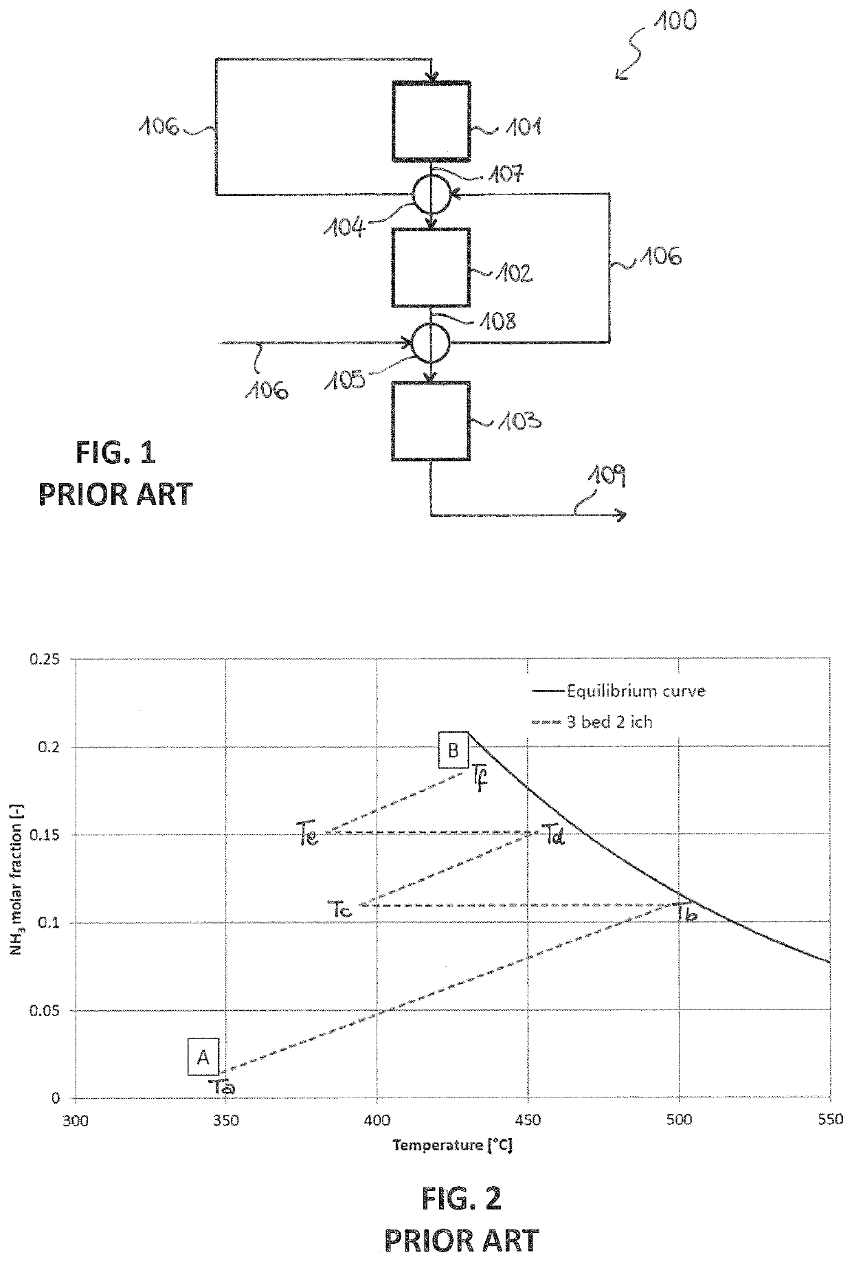
[0084]A prior art multi-bed reactor 100 is shown in FIG. 1. Said reactor 100 comprises three adiabatic catalytic beds 101, 102, 103 arranged in series, a first inter-bed heat exchanger 104 and a second inter-bed heat exchanger 105.

[0085]The operation of the reactor 100 is illustrated below.

[0086]A fresh make-up gas 106 passes through the second heat exchanger 105, wherein it is preheated by the effluent of the second bed 102, and subsequently through the first heat exchanger 104, wherein it is preheated by the effluent of the first bed 101. The so pre-heated make-up gas 106 enters the first bed 102, where it partially reacts to provide a first ammonia-containing stream 107. Said stream 107 is cooled inside the first heat exchanger 104 and the cooled effluent enters the second bed 102, where it further reacts to provide a second ammonia-containing stream 108. Similarly, said stream 108 is cooled in the second heat exchanger 105 before entering the third bed 103, which provides an amm...


PUM

PropertyMeasurementUnit
temperatureaaaaaaaaaa
volumeaaaaaaaaaa
adsorptionaaaaaaaaaa

Abstract

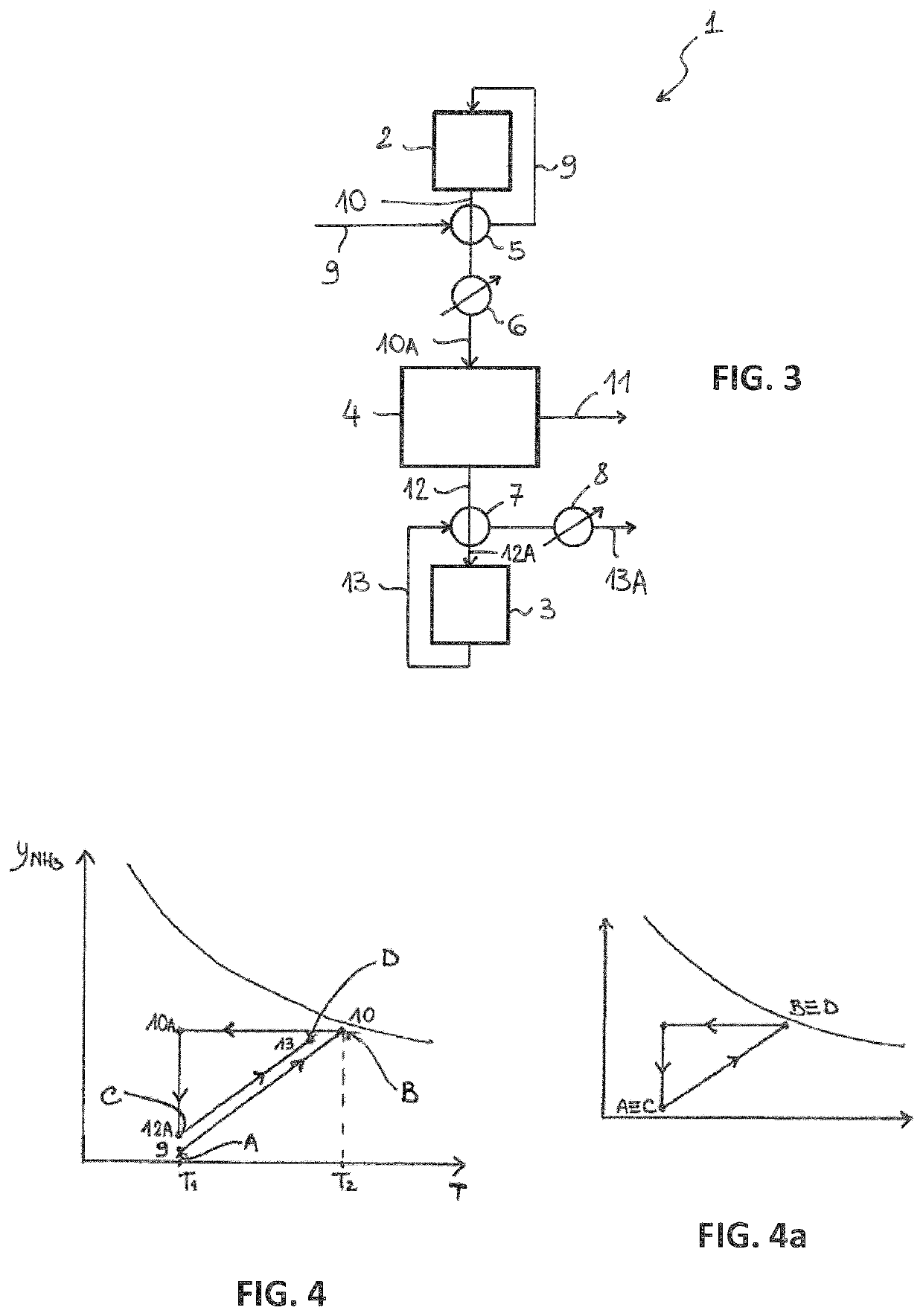
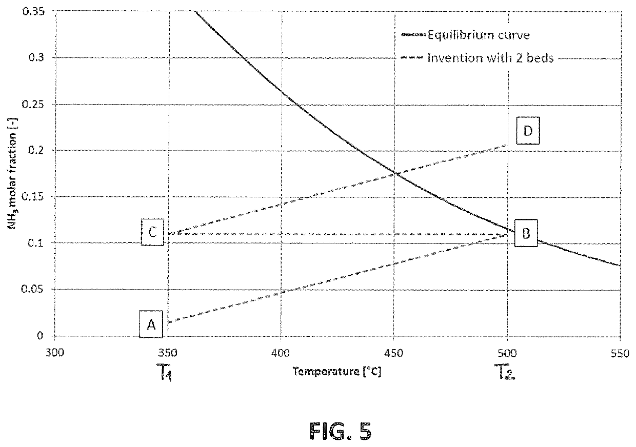
A process for the synthesis of ammonia from a make-up gas containing hydrogen and nitrogen, comprising at least two steps for the synthesis of ammonia, wherein: said reactive steps are performed in series and each of said reactive steps provides an ammonia-containing product gas; the second and any subsequent reactive step receives, as a feed stream, at least a portion of the product gas of the previous reactive step; an intermediate adsorptive step of ammonia is performed between consecutive reactive steps, so that the product gas of each step is depleted of ammonia prior to the subsequent reactive step of said series.

Description

FIELD OF THE INVENTION[0001]The invention relates to a process for the ammonia production by the catalytic conversion of a make-up synthesis gas.PRIOR ART[0002]The industrial production of ammonia involves the catalytic conversion of a synthesis gas (“make-up gas”) comprising hydrogen and nitrogen in a synthesis loop, according to the following reaction:3H2+N2⇄2NH3(ΔH0298=−92.4 kJ / mol)[0003]High equilibrium ammonia concentration could be achieved at high pressure and low temperature.[0004]However, for technical and economical limitations, the industrial ammonia production is carried out at temperature higher than 350° C. which ensures that the catalyst is active and at pressure lower than 200 bar, thus entailing a low equilibrium ammonia concentration.[0005]The unfavourable equilibrium of the reaction limits the ammonia concentration achievable under practical conditions to about 20% mol or less, which corresponds to a conversion per pass lower than 30%.[0006]The conversion per pass...

Claims


Application Information

Patent Timeline
Patent Type & Authority Applications(United States)
IPC IPC(8): C01C1/04B01J8/04
CPCC01C1/0464B01J8/0492C01C1/0417B01D53/04B01D53/0462B01D53/047B01D2256/16B01D2257/406C01C1/0447C01C1/0458C01C1/0488Y02P20/52C01C1/04
Inventor OSTUNI, RAFFAELEFERRINI, CRISTINAGOICOCHEA, JAVIER
Owner CASALE SA
Learn More