
Compact rotational gantry for proton radiation systems

a proton radiation system and compact technology, applied in radiation therapy, x-ray/gamma-ray/particle irradiation therapy, electrical equipment, etc., can solve the problems of reducing beam efficiency, needing large magnet apertures, and increasing the size and weight of magnets

Inactive Publication Date: 2020-10-01
VARIAN MEDICAL SYST PARTICLE THERAPY GMBH & CO KG
View PDF8 Cites 3 Cited by
  • Summary
  • Abstract
  • Description
  • Claims
  • Application Information

AI Technical Summary

Benefits of technology

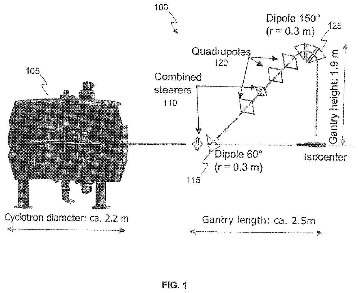
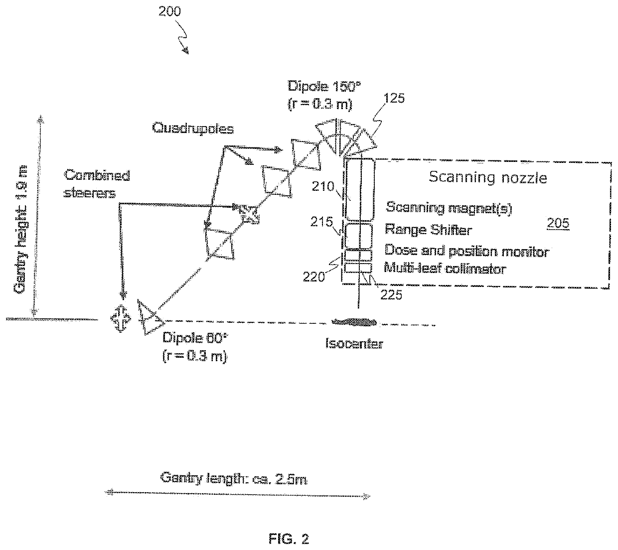
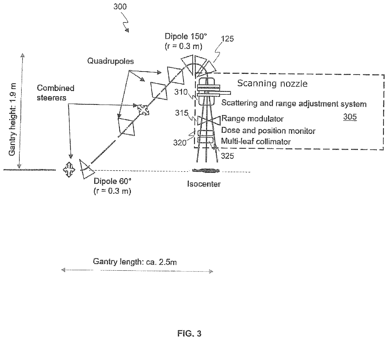
The present invention provides a rotational gantry designed for proton radiation therapy using a mono-energetic proton beam. The gantry includes a beam line transport system with bending magnets and quadrupole and steerer magnets for directing and focusing the proton beam. The energy variation of the beam is performed directly before the beam reaches the gantry. The gantry also includes a two-dimensional beam spreading system and an energy varying component for receiving the mono-energetic proton beam and varying its energy before reaching the isocenter of the gantry. The system is compact and can provide efficient and effective therapy.

Problems solved by technology

The large aperture further increases the size and weight of the magnets.
Additionally, a large fraction of the beam is stopped before the gantry when varying the beam energy causing the beam to diverge and spreading the beam energy in the process, leading to the need for large magnet apertures.
This leads to reduced beam efficiency, and these large high-energy beam losses also create the need for substantial concrete shielding, which also increases the building costs substantially.
Another main disadvantage of existing proton beamlines is the small beam transmission between the particle accelerator and the isocenter of the gantry.
Again, this leads to increased building costs and size.
Furthermore, existing particle therapy gantries change energy levels between treatment depths in the patient.
This fast ramping of the bending magnets generates various electrodynamic losses in the magnet conductor and other electrically conducting elements, which, in the case of superconducting magnets, leads to the risk of local hot-spots that can trigger a rapid transition in the magnet to the normal conducting state (“magnet quench”).
An alternative solution is the use of achromatic bending magnets that can accommodate a large range of energies of the particle beam; however, this solution is very expensive and requires large bore dipole or combined function magnets in combination with high quadrupole magnetic fields to re-focus the beam.
These large components lead to large gantry designs and structures.

Method used


Image

  • Compact rotational gantry for proton radiation systems
  • Compact rotational gantry for proton radiation systems
  • Compact rotational gantry for proton radiation systems

Examples


Embodiment Construction

[0015]Reference will now be made in detail to several embodiments. While the subject matter will be described in conjunction with the alternative embodiments, it will be understood that they are not intended to limit the claimed subject matter to these embodiments. On the contrary, the claimed subject matter is intended to cover alternative, modifications, and equivalents, which may be included within the spirit and scope of the claimed subject matter as defined by the appended claims.

[0016]Furthermore, in the following detailed description, numerous specific details are set forth in order to provide a thorough understanding of the claimed subject matter. However, it will be recognized by one skilled in the art that embodiments may be practiced without these specific details or with equivalents thereof. In other instances, well-known methods, procedures, components, and circuits have not been described in detail as not to unnecessarily obscure aspects and features of the subject mat...


PUM


Abstract

Embodiments of the present invention provide a rotational gantry designed to provide proton radiation therapy using a mono-energetic proton beam. The mono-energetic proton beam is transported by a beam line transport system having two or more bending magnets and a plurality of quadrupole and steerer magnets for directing and focusing the proton beam. Energy variation of the beam is performed directly before the beam reaches an isocenter of the gantry.

Description

FIELD[0001]Embodiments of the present invention generally relate to the field of particle therapy. More specifically, embodiments of the present invention relate to compact gantries used for particle therapy treatment systems.BACKGROUND[0002]To provide proton or particle therapy treatment to a patient, charged particles are directed to the patient on a treatment table at a chosen angle. A gantry including a beamline and bending magnets are used to bring the charged particle beam to the selected angle relative to the patient table. The charged particles are output from an accelerator and emitted into the gantry. Gantries used for particle therapy typically include normal-conducting magnets for bending the particle beam, which requires a gantry having a diameter on the order of 8 meters. Furthermore, the substantial weight of the bending magnets must be supported by the mechanical structure of the gantry.[0003]Moreover, the energy of the particle beam must be adjusted by introducing v...

Claims


Application Information

Patent Timeline
Patent Type & Authority Applications(United States)
IPC IPC(8): A61N5/10H05H13/00H05H7/04
CPCH05H13/005H05H2007/048A61N5/1045A61N5/1081H05H7/04A61N2005/1087A61N2005/1095H05H2007/002H05H7/001H05H2277/11
Inventor GODEKE, ARNOHEESE, JUERGENSCHILLO, MICHAEL
Owner VARIAN MEDICAL SYST PARTICLE THERAPY GMBH & CO KG
Learn More