
Particle accelerator beam bending magnet

A technology for deflecting magnets and accelerators, applied in the directions of accelerators, electrical components, etc., can solve the problem that the same kind of charged particle beam cannot be merged

Pending Publication Date: 2019-10-11
CHINA INSTITUTE OF ATOMIC ENERGY
View PDF0 Cites 2 Cited by
  • Summary
  • Abstract
  • Description
  • Claims
  • Application Information

AI Technical Summary

Problems solved by technology

[0005] Aiming at the deficiencies of the prior art, the present invention proposes a beam deflection magnet for a particle accelerator, with the purpose of solving the problem that the beams of the same charged particles with the same energy produced by the accelerator cannot be merged

Method used


Image

  • Particle accelerator beam bending magnet
  • Particle accelerator beam bending magnet
  • Particle accelerator beam bending magnet

Examples


Embodiment

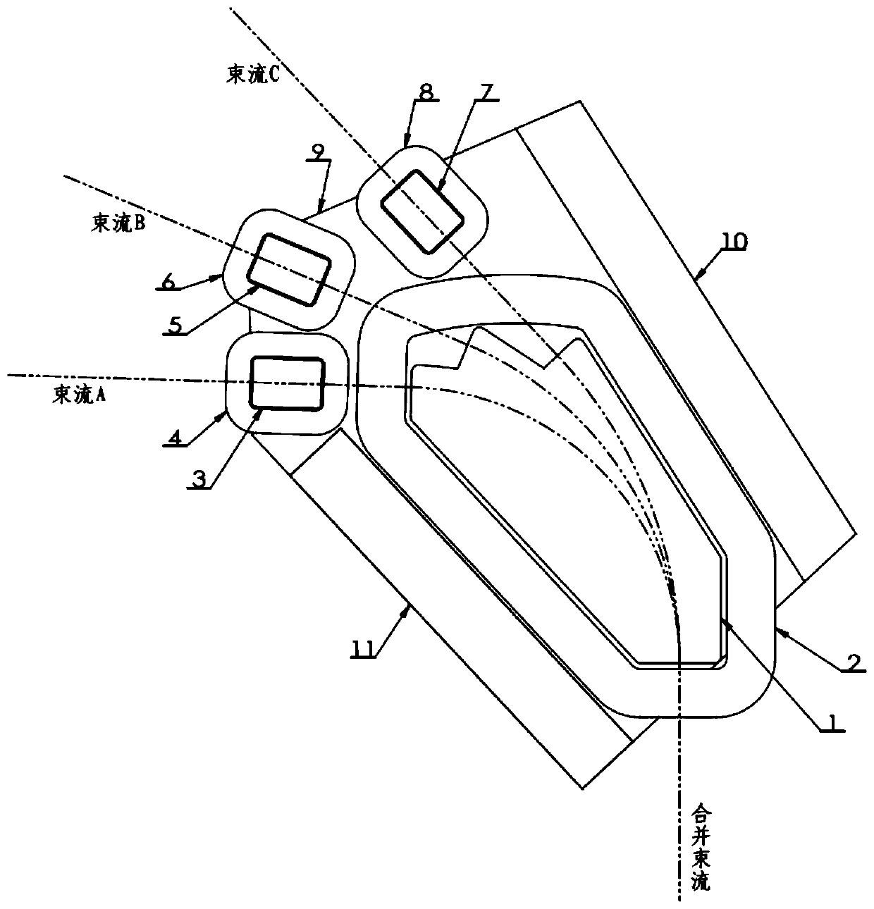
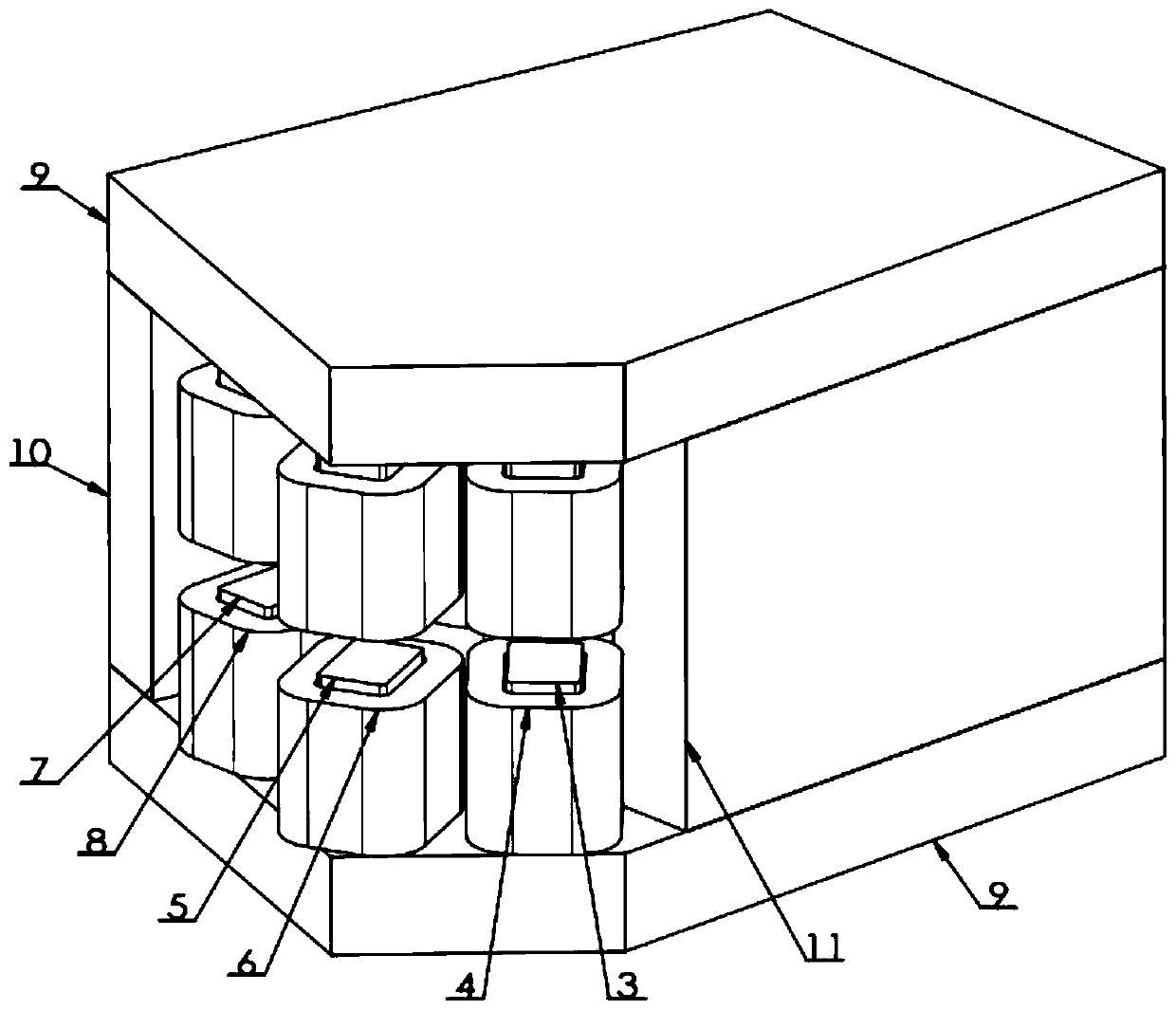
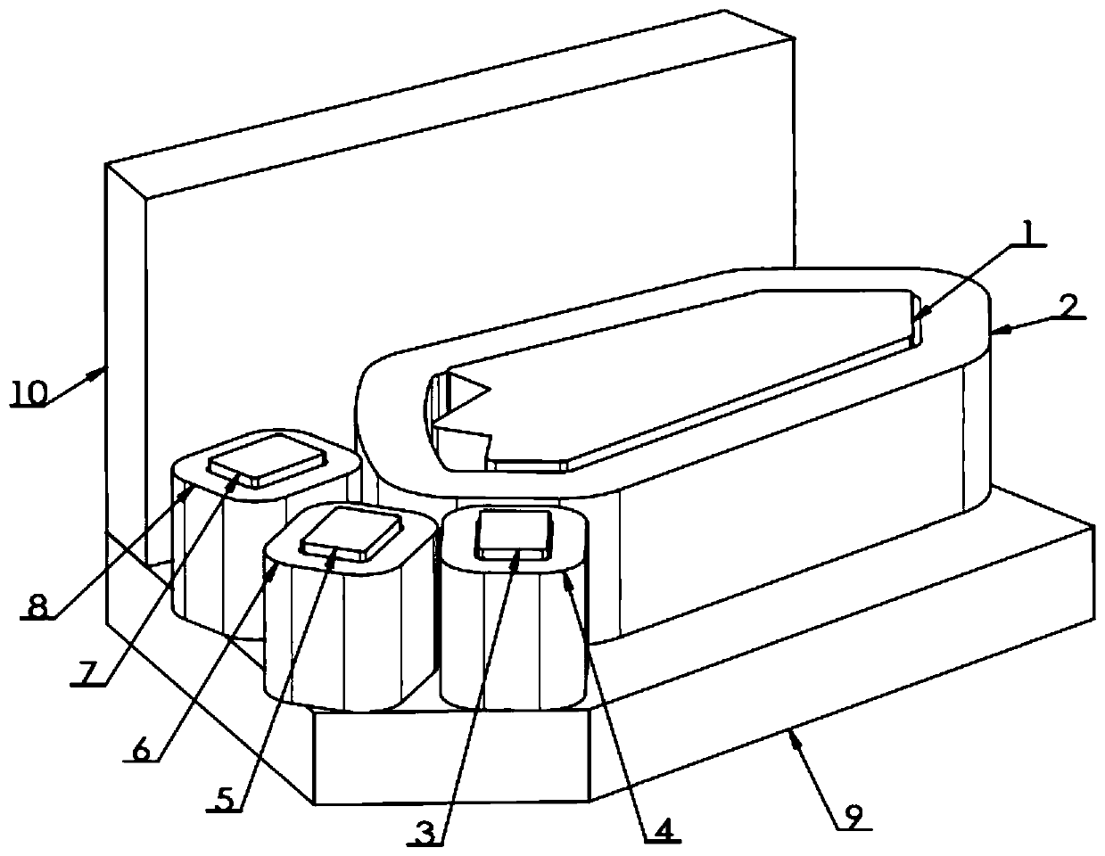
[0049] Use the accelerator beam of the present invention to combine the deflection magnet (such as figure 1 , 2 (Shown), after the three beams to be combined pass the deflection magnet, they can be combined into one combined beam. The main process of its function realization is as follows:

[0050] (1) Such as figure 1 , 2 , 3, 4, 5, the upper and lower yokes, side yoke A, side yoke B and main magnetic pole, guiding magnetic pole A, guiding magnetic pole B, guiding magnetic pole C, constitute the main magnetic field and 3 deflection magnetic fields of the deflection magnet Magnetic circuit. The magnetic circuit directional guides the magnetic field generated by the excitation coil, thereby generating a magnetic field of the required size and position distribution in the magnetic pole gap.

[0051] (2) Such as figure 1 , 2 , 3, 4, 5, the main coil, guide coil A, guide coil B, and guide coil C are all used in pairs. Each pair of coils are electrically connected in series in the sam...


PUM


Abstract

The invention discloses a particle accelerator beam bending magnet, comprising main magnetic poles (1), main coils (2), guiding magnetic poles, guiding coils, upper, lower, left and right magnetic yokes, and multiple charged particle beams with properly different energy or particle types, which form a main magnetic field and a guiding magnetic field component; the multiple charged particle beams with properly different energy or particle types enter the bending magnet from different directions, and combined into a beam with the same track and direction after passing through the bending magnet;the main magnetic poles (1), main coils (2), guiding magnetic poles and guiding coils are used in an upper and lower paired manner, a certain gap is reserved between the upper and lower magnetic poles in each pair, a vacuum pipe is installed in the gap, and the beam can pass through the vacuum environment in the vacuum pipe. According to the particle accelerator beam bending magnet provided by the invention, the effect that the multiple beams are combined into one beam is achieved, the domestic blank is filled, and the long-term difficult problem that the particles with the same type and thesame energy cannot be combined into the same beam due to the same bending radius is solved.

Description

Technical field [0001] The invention relates to the technical field of particle accelerators, in particular to a particle accelerator beam deflection magnet. Background technique [0002] When the beam generated by the particle accelerator needs to be deflected, a deflection magnet is usually used, and the magnetic field generated by energizing the deflection magnet can deflect the charged particle beam. The deflection magnet generally uses pure iron material to make the excitation core, which is the magnetic pole of the deflection magnet; uses pure iron or low carbon steel material to make the yoke (peripheral magnetic circuit); the magnetic field generated in the gap between a pair of magnetic poles is used as a charged The particle beam deflects the magnetic field. [0003] In actual scientific research and production, sometimes it is desirable to deflect multiple charged particle beams generated by accelerators and merge them into one beam. However, the existing deflection ma...

Claims


Application Information

Patent Timeline
Patent Type & Authority Applications(China)
IPC IPC(8): H05H7/04
CPCH05H7/04H05H2007/046Y02E30/10
Inventor 邢建升
Owner CHINA INSTITUTE OF ATOMIC ENERGY
Learn More