Surface cleaning apparatus with two-stage collection
a cleaning apparatus and two-stage technology, applied in the field of two-stage cleaning apparatus, can solve the problems of increasing the battery life or runtime of the apparatus without reducing cleaning performance, and achieve the effect of reducing the power requirements of the suction source, increasing the battery life or runtime of the apparatus without reducing cleaning performance, and reducing the cost of the apparatus
- Summary
- Abstract
- Description
- Claims
- Application Information
AI Technical Summary
Benefits of technology
Problems solved by technology
Method used
Image
Examples
first embodiment
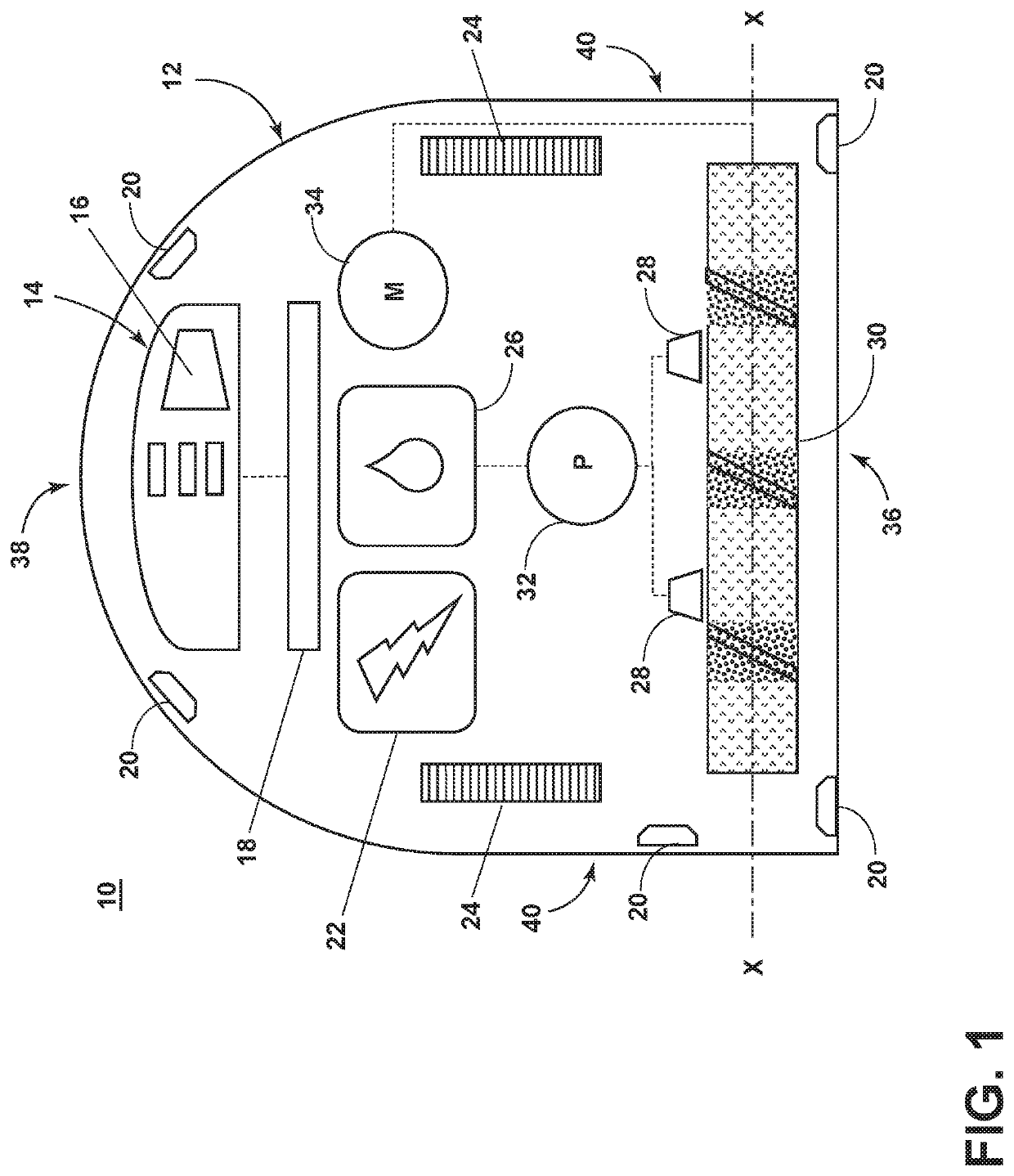
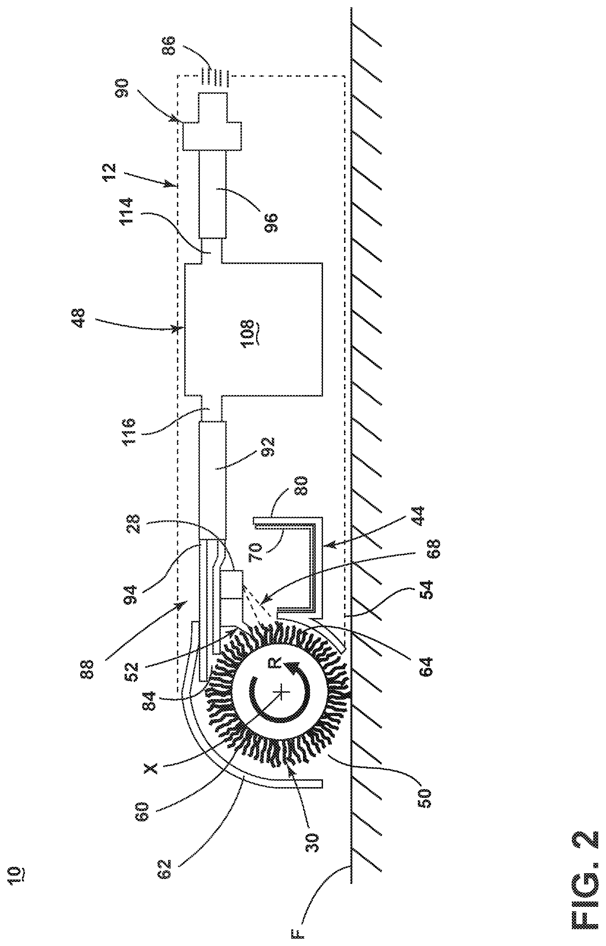
[0094]The first collection area 44 can be any type of collection area, cup, tray, bin, or tank suitable for the purposes described herein, including the collection of debris and liquid. The first collection area 44 can generally receive liquid and debris in the same manner as described above for the In the illustrated embodiment, the first collection area 44 comprises a receptacle 140 and a collection tray 142 configured to fit within the receptacle 140. The collection tray 142 includes a plurality of openings 144 and acts as a strainer to separate the dirty liquid from the debris. The collection tray 142 is configured to collect the debris, including hair, while draining liquid, and optionally some smaller-sized debris, into the receptacle 140 for eventual collection in the second collection area 48, as described in further detail below. The second collection area 48 can primarily collect liquid. Any debris collected in the second collection area 48 can be small enough to pass thr...
third embodiment
[0107]FIG. 13 is a perspective view of a surface cleaning apparatus shown as a sweeper and generally designated 210. As discussed in further detail below, the sweeper 210 is provided with various features and improvements, which are described in further detail below. As illustrated herein, the sweeper 210 can be an upright multi-surface sweeper having a housing that includes an upright handle assembly or body 212 and a cleaning foot or base 214 mounted to or coupled with the upright body 212 and adapted for movement across a surface to be cleaned. The sweeper 210 includes a fluid delivery system and a two-stage collection system, which are described in further detail below, and which can include components supported on either one or both of the body 212 and base 214.
[0108]The upright body 212 can comprise a handle 216 and a frame 218. The frame 218 can comprise a main support section supporting at least a supply tank 220, and may further support additional components of the body 21...
second embodiment
[0148]FIG. 16 is a schematic view of another embodiment of the sweeper 210. This embodiment of the sweeper 210 is substantially the same as the embodiment described with respect to FIGS. 13-15 save for having a two-stage collection system substantially the same as the embodiment described with respect to FIGS. 9-12, and like elements are indicated with the same reference numerals. In this embodiment, the sweeper 210 is configured to strain out debris of a certain size from the dirty liquid collected in the first collection area 274, and to pump the dirty liquid into the second collection area 278 in a similar manner as the second embodiment described with respect to FIGS. 9-12, and comprises, among other elements of the collection system described with respect to FIGS. 9-12, the receptacle 140, the collection tray 142 with the plurality of openings 144 to act as a strainer to separate the dirty liquid from the debris, and the pump 154 in fluid communication with the receptacle 140 f...
PUM
 Abstract
Description
Claims
Application Information
 - R&D
- Intellectual Property
- Life Sciences
- Materials
- Tech Scout
- Unparalleled Data Quality
- Higher Quality Content
- 60% Fewer Hallucinations
Browse by: Latest US Patents, China's latest patents, Technical Efficacy Thesaurus, Application Domain, Technology Topic, Popular Technical Reports.
© 2025 PatSnap. All rights reserved.Legal|Privacy policy|Modern Slavery Act Transparency Statement|Sitemap|About US| Contact US: help@patsnap.com


