
Cable Assembly

a technology of cable and connector, which is applied in the direction of insulated conductors, cable connections, coupling devices, etc., can solve the problems of inability to guarantee direct contact, limited degree of heat exchange which can be obtained with such an arrangement, and inability to achieve direct contact, etc., to achieve the effect of reducing the damage of electric and/or fluidic contacts as well as the mechanical guard due to accidental drop of the connector, and achieving good results

Active Publication Date: 2020-09-24
HUBERSUHNER AG
View PDF0 Cites 23 Cited by
  • Summary
  • Abstract
  • Description
  • Claims
  • Application Information

AI Technical Summary

Benefits of technology

The patent text describes a cable assembly with a design that allows the components inside to move relative to each other, resulting in a cable with lower bending stiffness. The design also allows for easy displacement without reducing cooling capacity. Additionally, the design includes a special type of fluid path that can handle impact loads and efficiently distribute them across the connector without interfering with its main function. The technical effects of this design include improved handling, reduced bending stiffness, and improved impact absorption.

Problems solved by technology

Following Joule's Law of heating, due to the high currents usually occurring in such cable assemblies during operation high amounts of thermal energy may be generated, constituting a risk for the cable assembly as well as for the devices interconnected with it.
The degree of heat exchange which can be obtained with such an arrangement is limited as the contact faces between cable cores and cooling pipes are relatively small.
In addition, this presupposes direct contact is needed and cannot be guaranteed if the cable is bent.
Such cables have a relatively complex inner architecture to meet the high demands posed by the special types of cooling agents.
Hence they are complicated to manufacture, which has an adverse effect in terms of production costs.
Thus, although such cables are reasonable in the field of superconducting systems, they are not really suited for other applications.
Due to the metal pipe the resulting power cable has a very limited flexibility.
This decreases the efficiency of the cooling system.
However, such filler material will increase resistance to bending of a cable and hence deteriorate handling of the cable.

Method used


Image

  • Cable Assembly
  • Cable Assembly
  • Cable Assembly

Examples


second embodiment

[0107]FIGS. 8a and 8b show a cable 10 that has a concentric structure. In the center of the cable 10 a stranded conductor 12 is arranged which comprises a first sheath 13 that provides electrical insulation as well as it is impermeable for cooling fluid. A first electrically insulating tube 26 which is impermeable for cooling fluid envelops the first sheath 13, spaced a distance apart from the first sheath 13. The first sheath 13 and the first electrically insulating tube 26 are interposed with first spacers 25 arranged around the center conductor 12 in order to define a first interstitial space 15a between the first sheath 13 and first electrically insulating tube 26 to convey a cooling fluid in a first direction along the cable. A concentric layer of multiple conductors 28a is arranged such that it envelops the first electrically insulating tube 26. A second electrically insulating tube 27 is be arranged such that it envelops the concentric layer of multiple conductors 28a. Second...

embodiment 1

[0109]FIG. 13 and FIG. 14 show a further embodiment of a cable assembly 1 according to the invention with a similar setup like the embodiment 1 shown in FIG. 11 and FIG. 12. Yet, the cable assembly 1 shown in FIG. 13 and FIG. 14 comprises only one cable 10 interconnected with a connector 30. In order to obtain temperature regulation of the cable assembly 1—respectively cooling of the conductors 12—, cooling fluid (indicated by the dashed arrow) provide by a tube (not shown) can enter a chamber 32 arranged within the connector 30 via a second port 34 and circulate around conductors 12a, 12b arranged inside of the cable hose 11 and extending through the chamber 32 to contact members 31 (only one contact member is visible). Thus, the portions of the conductors 12a, 12b arranged within the chamber 32 can be prevented from overheating. As well, the chamber 32 comprises a first port 33 that is interconnected with the cable hose 11 and through which the cooling fluid can leave the chamber ...


PUM

PropertyMeasurementUnit
distanceaaaaaaaaaa
temperatureaaaaaaaaaa
electrical currentsaaaaaaaaaa

Abstract

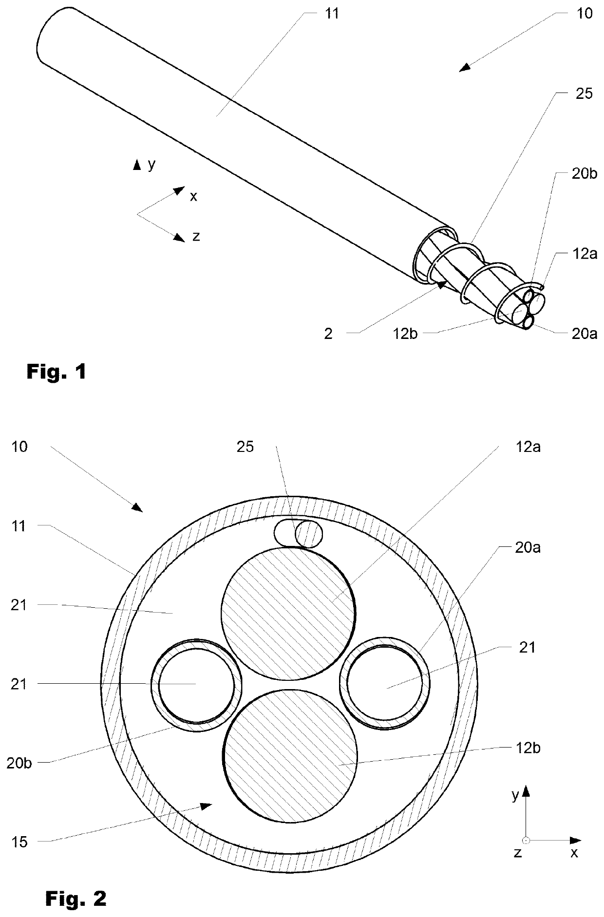
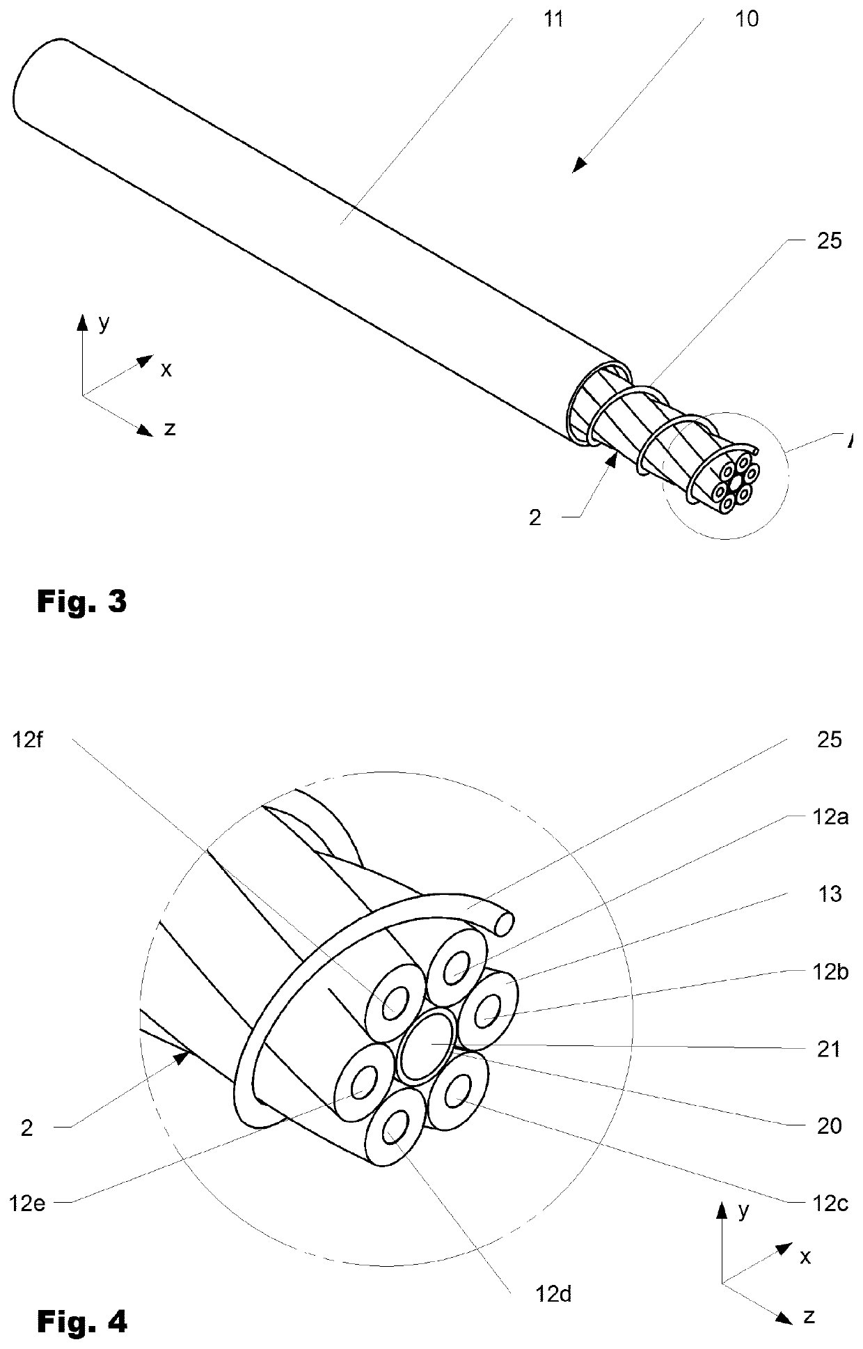
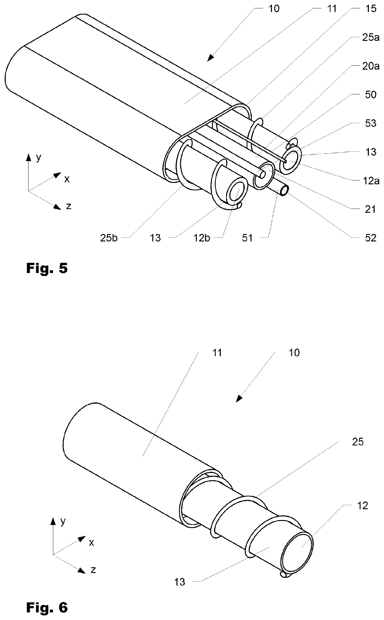
The invention is directed to a cable assembly (10, 10a-b), comprising a cable (10, 10a-b) with a cable hose (11, 11a-b) and at least one conductor (12, 12a-f) arranged therein. The cable hose (11, 11a-b) is spaced a distance apart from the conductor (12) forming a first interstitial space (15,a-b) between the at least conductor (12) and the cable hose (11, 11a-b). At least one tube (20, 20a-b) for conveying of a cooling fluid (21), and a connector (30) comprising at least one contact member (31) interconnected to the at least one conductor (12) and a chamber (32). Said chamber (32) comprises a first port (33) which is interconnected to the first interstitial space between the at least one conductor (12, 12a-f) and the cable hose (11, 11a-b) and a second port (34a, 34a-b) which is interconnected to the at least one tube (20, 20a-b).

Description

FIELD OF THE INVENTION[0001]The present invention is directed to a cable assembly, in particular to a cable assembly with a temperature regulating means.BACKGROUND OF THE INVENTION[0002]A wide range of publications with regard to cable assemblies that comprise temperature regulation means is known. Such cable assemblies are e.g. used for conducting high electrical currents, as for power supply for charging batteries of electrical vehicles. Following Joule's Law of heating, due to the high currents usually occurring in such cable assemblies during operation high amounts of thermal energy may be generated, constituting a risk for the cable assembly as well as for the devices interconnected with it. One way to obtain high currents while keeping joule heating low is to reduce the electrical resistance of the conductor. When using conventional conductors this is typically done by increasing the conductor's diameter and / or trying to keep the conductor at relatively low temperatures, as in...

Claims


Application Information

Patent Timeline
Patent Type & Authority Applications(United States)
IPC IPC(8): H01B7/42H01R13/506H01R13/00
CPCB60L53/16B60L53/302H01R13/005H01B7/423H01R27/00B60L53/18H01R13/506H01R2201/26H01B7/425H01R9/11Y02T90/14Y02T10/7072Y02T10/70Y02T90/12
Inventor CANTZ, THOMASCASANOVA, RETO
Owner HUBERSUHNER AG
Learn More