
Fluid container having a device for fill level monitoring

a technology for monitoring devices and fluid containers, which is applied in the direction of measurement devices, level indicators, instruments, etc., can solve the problems of increasing the dimensions of fluid containers with disadvantages in terms of installation space, blocking or jamming position encoders cannot be reliably detected, and gradual leakage, on the other hand, could remain undetected for a long tim

Pending Publication Date: 2020-09-17
CONTINENTAL TEVES AG & CO OHG
View PDF0 Cites 0 Cited by
  • Summary
  • Abstract
  • Description
  • Claims
  • Application Information

AI Technical Summary

Benefits of technology

The invention provides a device for detecting the position of a magnet element in a fluid container, using a Hall element. This allows for continuous detection of the position, rather than just at a fixed point. The device can also detect leaks based on positional variations of the position encoder. This makes it possible to accurately measure the actual residual volume of the fluid container, reducing the amount of fluid needed and the size of the container. The device can be calibrated and used in different scenarios, such as a brake fluid container for a vehicle. The technical effects of the invention include improved accuracy in measuring the position of the magnet element and the ability to detect leaks in real-time.

Problems solved by technology

Since reliability of braking nevertheless has to be ensured for a defined period of time or distance, a safety supply of brake fluid is carried in the fluid container beneath the switching position, which increases the dimensions of the fluid container with disadvantages in terms of the required installation space.
In this regard, blocking or jamming of the position encoder cannot be reliably detected, for example.
Gradual leakage, on the other hand, could remain undetected for a long period of time.

Method used


Image

  • Fluid container having a device for fill level monitoring
  • Fluid container having a device for fill level monitoring

Examples


first embodiment

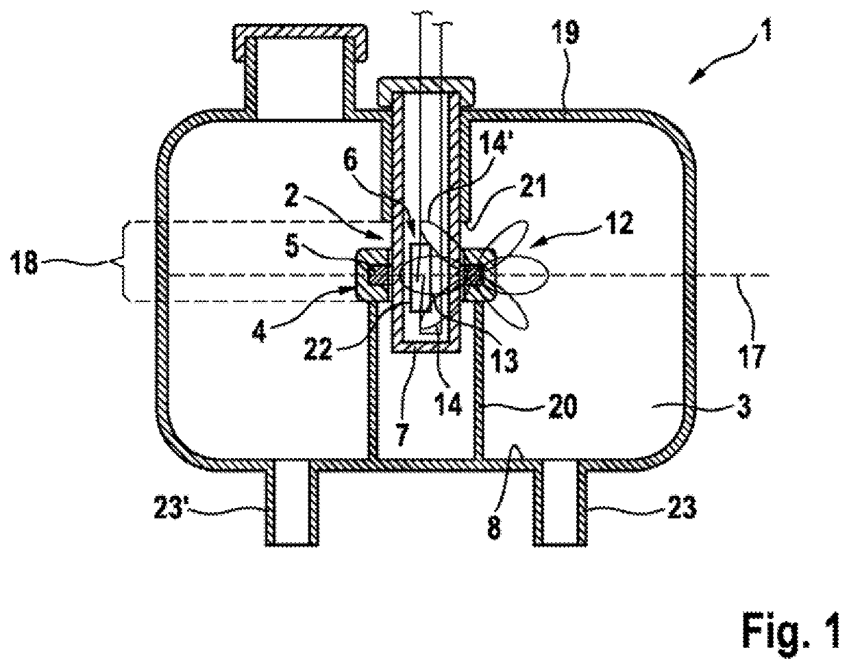
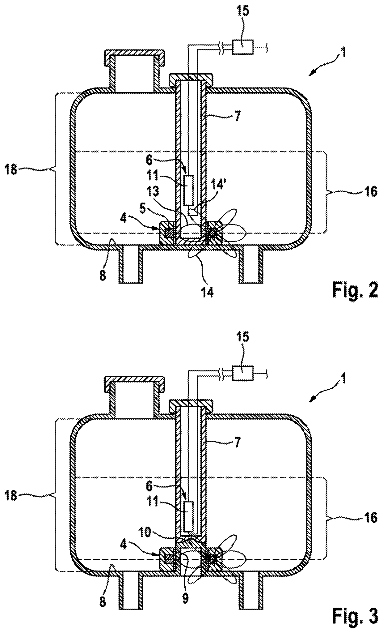
[0015]A first embodiment according to the invention of the fluid container 1 is shown in simplified form in FIG. 2. By contrast to the above-described known embodiment, the signal unit 6 has a Hall element 11 which is arranged in the guide tube 7. The guide tube 7 is designed so as to be extended such that it reaches as far as the base 8 of the housing 19 of the fluid container 1. Moreover, the movement-limiting stops 20,21 are not present, as a result of which the movement range 18 of the position encoder 4 extends over the entire possible fill height of the fluid container 1.

[0016]As is known, a Hall element through which current flows generates an output voltage which is proportional to the product of magnetic flux density and current. Said Hall element hereby has, by contrast to the reed switch, an analog behavior. The fact that the flux densities of the main and side lobes 13,14,14′ of the magnetic field 12 generated by the magnet element 5 are constant and known means that, fr...

second embodiment

[0018]FIG. 3 shows a second embodiment according to the invention of the fluid container 1. By contrast to the embodiment according to FIG. 2, the guide tube 7 is of shortened design. At the same time, a projection 9 rises from the base 8 in the direction of the guide tube 7 and is provided for continuing the position encoder 4 as far as the base 8.

[0019]For secure mounting of the guide tube 7 and unhindered guidance of the position encoder 4, provision is made between the guide tube 7 and the projection 9 of a form-fitting centering device 10, which, when the guide tube 7 is mounted, forcibly ensures coaxial alignment of the two with respect to one another.

[0020]In the embodiment shown, the centering device 10 is formed as a conical elevation at the end of the projection 9 that engages into a complementary depression at the end of the guide tube 7. It goes without saying that other functionally equivalent variants of the centering device 10 are also permissible within the scope of ...


PUM


Abstract

A fluid container having a device which is arranged in an interior space within the fluid container and which serves for monitoring the fill level of a fluid, the device comprising a linearly movable position encoder having a magnet element, the position of which correlates with the fill level of the fluid in the fluid container, and comprising a signal unit, which generates at least one electrical signal in a manner dependent on the position of the magnet element.

Description

CROSS REFERENCE TO RELATED APPLICATIONS[0001]This application claims priority to PCT International Application No. PCT / EP2018 / 078727, filed Oct. 19, 2018, which claims priority to German Patent Application No. DE 10 2017 222 672.2, filed Dec. 13, 2017, wherein the contents of such applications are incorporated herein by reference.TECHNICAL FIELD[0002]Fluid containers having a device for monitoring a fill level of the fluid.TECHNICAL BACKGROUND[0003]DE 10 2010 042 646 A1 has disclosed for example a fluid container designed as a brake fluid container of a motor vehicle brake system. The fluid container has a device for detecting the minimum fill level of the brake fluid introduced. For this purpose, the device has a signal unit having an inexpensive and operationally reliable reed switch, which is activated by an annular magnet and in the process closes an electrical circuit. The reed switch is arranged in the container at the height of the permissible minimum fill level in a vertical...

Claims


Application Information

Patent Timeline
IPC IPC(8): G01F23/72
CPCG01F23/72G01F23/74G01F23/0007
Inventor SCHLICHT, STEPHANKRÄMER, HORSTRÜFFER, MANFREDKREBS, WERNEROTTMANN, SWEN
Owner CONTINENTAL TEVES AG & CO OHG
Learn More