
Improved surgical mouth gag

a surgical and mouth gag technology, applied in the field of improved surgical mouth gags, can solve the problems of creating complete obstruction of the upper airways, preventing the passage of air to the lungs, and the inability to have suitable exposure of the “hard palate", so as to achieve the effect of safely and effectively moving apart the walls of the oral cavity

Active Publication Date: 2020-09-17
FOND IRCCS CA GRANDA OSPEDALE MAGGIORE POLICLINICO
View PDF0 Cites 4 Cited by
  • Summary
  • Abstract
  • Description
  • Claims
  • Application Information

AI Technical Summary

Benefits of technology

The invention helps to expose all the structures in the mouth, throat, and nasal cavity that need surgery. It reduces the risk of dental damage and allows the tongue to move freely without being obstructed. This is important for patients who need to have their tongue or tonsils removed.

Problems solved by technology

When the muscles of the soft palate, of the uvula, of the lateral pharyngeal walls and of the tongue are not able to guarantee sufficient rigidity for the walls of the upper airways (of the pharyngeal tract in particular), the relaxed tissues, collapsing, can simply move closer and vibrate as air passes through, causing snoring or, in more severe cases, create complete obstruction of the upper airways and prevent the passage of air to the lungs, producing apnoea.
A drawback of these traditional mouth gags, that make use of resting on the anterior dental elements of the upper arch, is the impossibility to have suitable exposure of the “hard palate”-“soft palate” junction, which is of utmost importance in modern surgery for snoring and obstructive apnoea of retropalatal origin.
A further drawback of known mouth gags is that they do not allow the suitable and bilateral exposure of the base of the tongue at glossotonsillar sulcus level (transition site between the lingual tonsil and palatine tonsil) as they are not able to simultaneously advance the base of the tongue fully, i.e. the median portion and both the lateral portions.
A further drawback of known mouth gags is that, by resting on the upper incisors, as well as preventing the direct viewing of the junction between the hard and soft palate, they can cause lesions to these dental elements during attempts to obtain more suitable exposure.

Method used


Image

  • Improved surgical mouth gag
  • Improved surgical mouth gag
  • Improved surgical mouth gag

Examples


Embodiment Construction

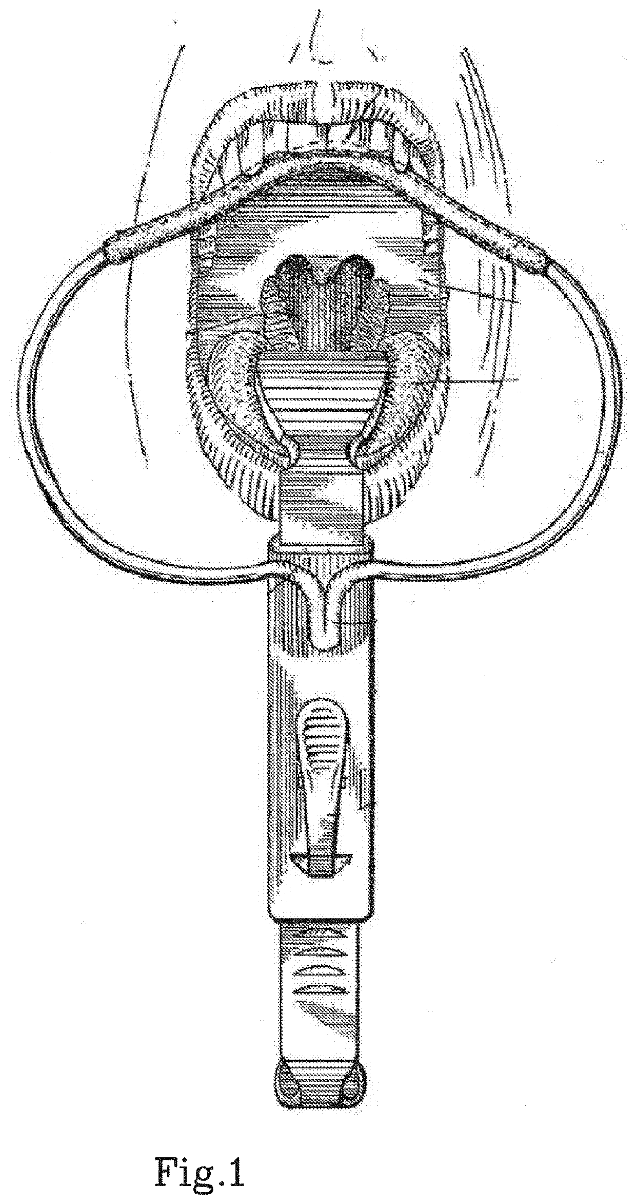
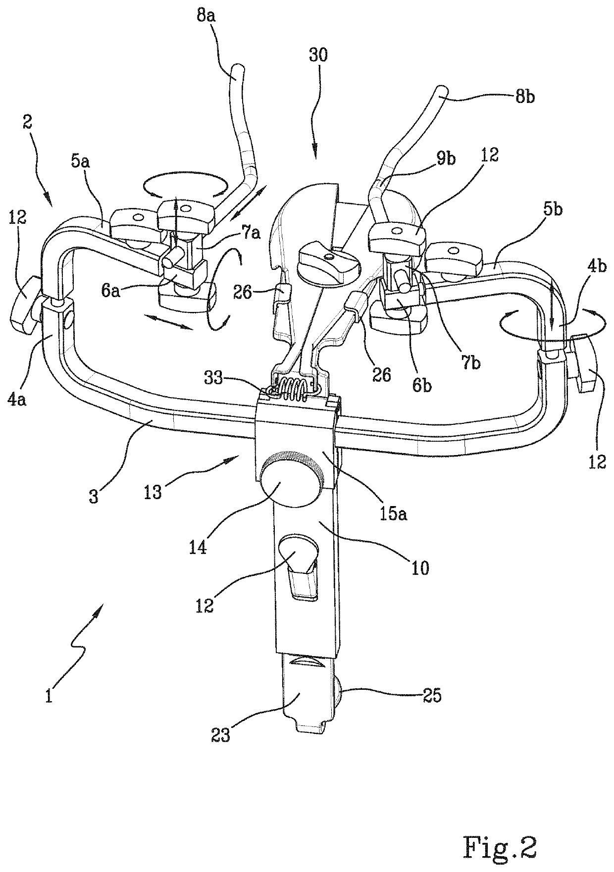
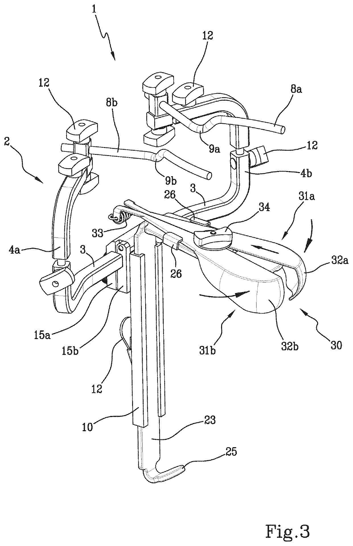
[0045]In a first embodiment, the present invention describes a surgical mouth gag 1 for the exposure of the palatal and oropharyngeal region of a patient comprising a perioral supporting arch or frame 2 adapted to be arranged, during use, around the mouth of the patient. In particular, the frame 2 is larger than the maximum aperture of the mouth, so as to keep the mouth in that position.

[0046]As indicated below, the term “vertical” means a substantially similar, but not identical direction to the arrangement of the teeth, a vertical direction being defined in the present description as “upper” or “above”, i.e. towards the upper jaw, and the opposite vertical direction being defined as “lower” or “downwards”, i.e. mandibular towards the lower jaw. In other words, the vertical direction lies on the median sagittal plane (arranged in the vertical direction and passing through the interparietal suture and so as to divide the skull into two specular halves, right and left).

[0047]“Lateral...


PUM


Abstract

The present invention describes an improved surgical mouth gag for the exposure of the palatal and oropharyngeal region of a patient comprising a frame (2) adapted to be arranged in use around the mouth of the patient and a tongue depressor system (21, 30) insertable in the oral cavity of the patient and movable with respect to the frame (2), the tongue depressor blade (21, 30) comprising two elements articulated to each other, able to mobilise fully in a graduated way the entire tongue base both in the caudal and posterior-anterior direction. The metal arch (2) supports and anchors the aforesaid tongue depressor system, by resting on the upper premolar and molar teeth (respecting the incisors) and acts as an anterior window adapted to guarantee both optimal exposure of the palatal structures and of the isthmus of the fauces and to facilitate palatal and oropharyngeal surgery in general and that of obstructive sleep disorders in particular.

Description

TECHNICAL FIELD[0001]The present invention relates to an improved surgical mouth gag comprising a metal arch and a tongue depressor blade able to obtain optimal exposure of the palatal structures and of the isthmus of the fauces and to facilitate the performance of palatal and oropharyngeal surgery in general and that of obstructive sleep disorders in particular.PRIOR ART[0002]Normally, the muscles attached to the walls of the upper airways also have the task of keeping the respiratory tracts open during inspiration so as to allow the flow of air into the lungs. When the muscles of the soft palate, of the uvula, of the lateral pharyngeal walls and of the tongue are not able to guarantee sufficient rigidity for the walls of the upper airways (of the pharyngeal tract in particular), the relaxed tissues, collapsing, can simply move closer and vibrate as air passes through, causing snoring or, in more severe cases, create complete obstruction of the upper airways and prevent the passage...

Claims


Application Information

Patent Timeline
IPC IPC(8): A61B1/24A61B1/32
CPCA61B1/24A61B1/32A61B13/00
Inventor MANTOVANI, MARIOPIGNATARO, LORENZORINALDI, VITTORIO
Owner FOND IRCCS CA GRANDA OSPEDALE MAGGIORE POLICLINICO
Learn More