
LED lighting apparatus

Active Publication Date: 2020-09-03
XIAMEN ECO LIGHTING CO LTD
View PDF0 Cites 2 Cited by
  • Summary
  • Abstract
  • Description
  • Claims
  • Application Information

AI Technical Summary

Benefits of technology

The patent text describes a device that prevents light from passing through certain parts of the device. The technical effect of this invention is to improve the functionality and accuracy of the device by controlling the passage of light.

Problems solved by technology

Their shipping often causes problems particularly through global movement.

Method used


Image

  • LED lighting apparatus
  • LED lighting apparatus
  • LED lighting apparatus

Examples


Embodiment Construction

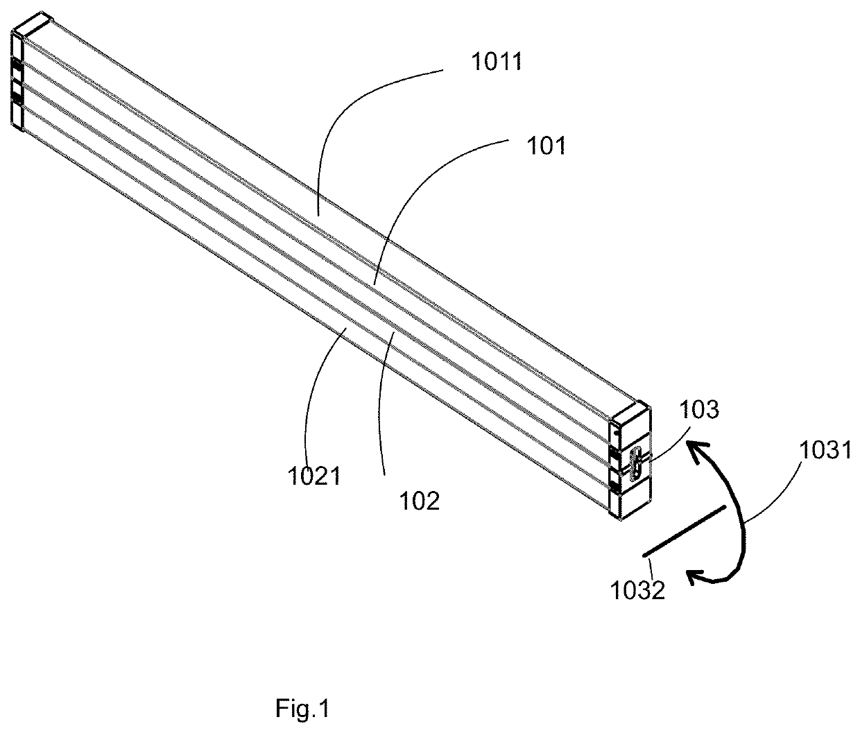
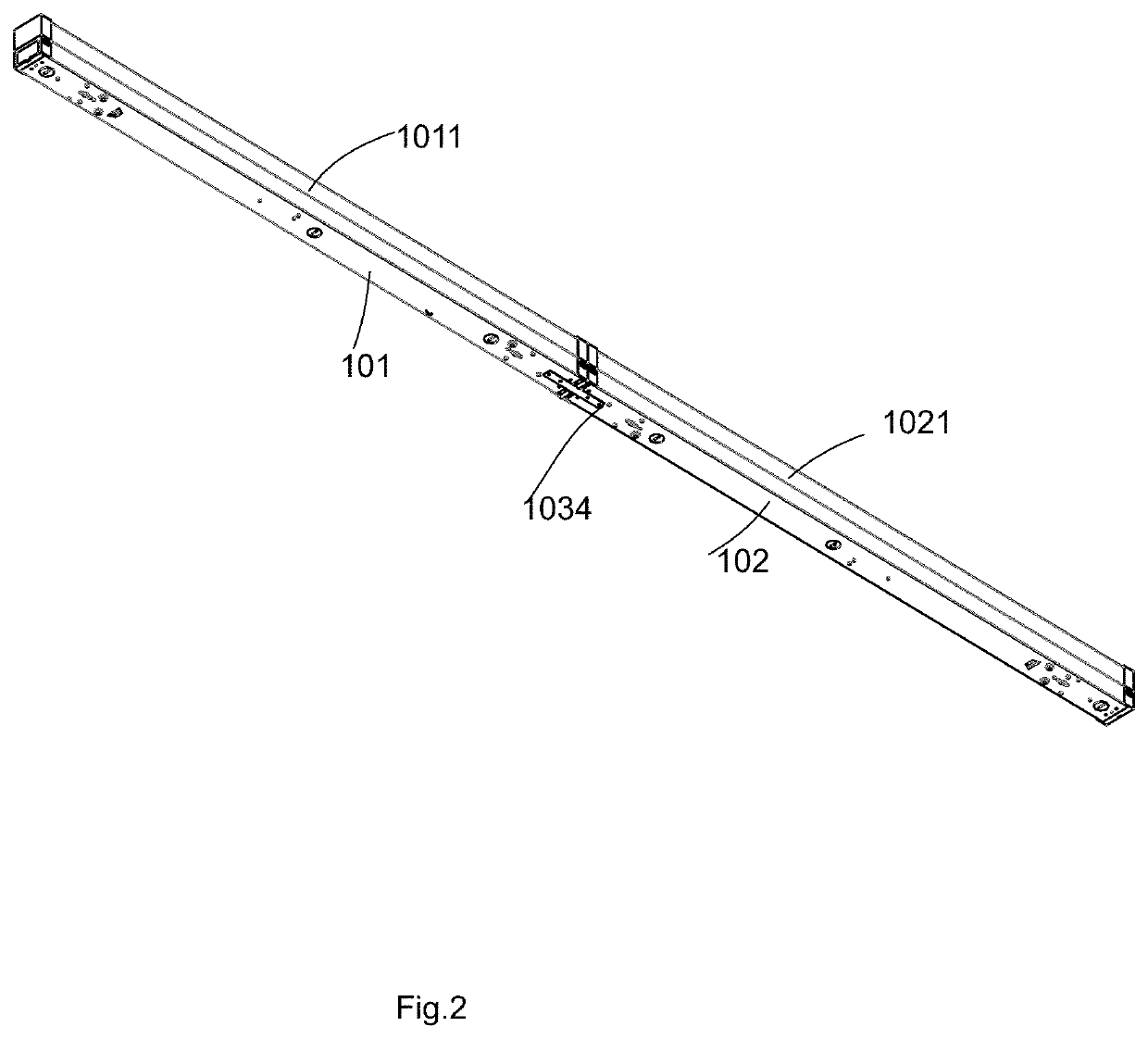
[0043]Please refer to FIG. 5A and FIG. 5B, a lighting apparatus has a first tube section 9950, a second tube section 9952 and a rotation structure 9951.

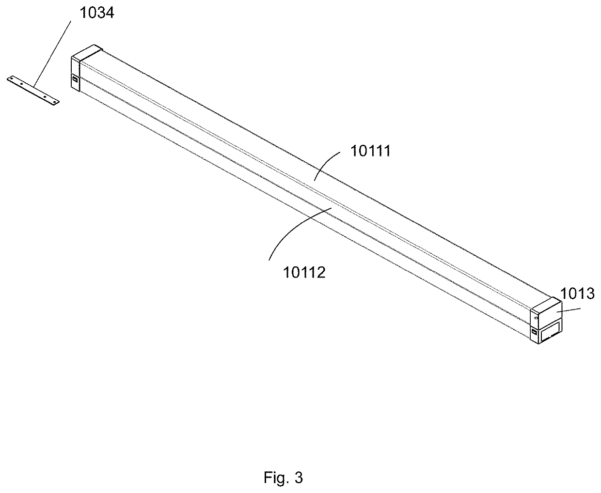
[0044]The first tube section 9950 has a first section housing 9953, a first light passing cover 9954, and a first light source 9957. The first section housing 9953 and the first light passing cover 9954 form a first container 9959 enclosing the first light source 9957. The first light is emitted from the first light source 9957 passing through the first light passing cover 9954.

[0045]The second tube section 9952 has a second section housing 9955, a second light passing cover 9956, and a second light source 9958. The second section housing 9955 and the section light passing cover 9956 form a second container 9960 enclosing the first light source 9952. A second light is emitted from the second light source 9958 passing through the second light passing cover 9956.

[0046]The rotation structure 9951 is connecting to a first rotation end 99...


PUM


Abstract

A LED tube has a first tube section and a second tube section. The first tube section and the second tube section are connected with a rotation structure. With the rotation structure, the first tube section and the second tube section may be rotated with respect to each other along a rotation axis.

Description

RELATED APPLICATION[0001]The present application claims priority of a provisional application of U.S. Patent Application No. 62 / 812,709.FIELD OF INVENTION[0002]The present invention is related to a light tube apparatus, and more particularly related to a light tube apparatus that has multiple operation modes.BACKGROUND[0003]Light tubes are widely used in modern life. When LED technologies keep developing, more and more light tubes use LED components to implement light tubes to achieve high energy efficiency and other advantages of LED technologies.[0004]Light tubes usually are designed with elongated shapes. Their shipping often causes problems particularly through global movement. It is important and beneficial to develop flexible light tubes to be more convenient and cost effectiveSUMMARY OF INVENTION[0005]In some embodiments, a lighting apparatus includes a first tube section, a second tube section and a rotation structure.[0006]The first tube section has a first section housing,...

Claims


Application Information

Patent Timeline
IPC IPC(8): F21V21/30F21V15/015F21V23/00
CPCF21V21/30F21V15/015F21V23/003F21Y2103/10F21Y2115/10
Inventor CHEN, CHUNTENGZHANG, LEI
Owner XIAMEN ECO LIGHTING CO LTD
Learn More