Electrostatic image developing toner and image forming method

a technology which is applied in the field of developing toner and developing toner, can solve the problems of low productivity, limit to energy saving, and low image strength of formed toner image, and achieve the effect of high image strength

Inactive Publication Date: 2020-08-20
KONICA MINOLTA INC
View PDF0 Cites 0 Cited by
  • Summary
  • Abstract
  • Description
  • Claims
  • Application Information

AI Technical Summary

Benefits of technology

[0011]The present invention has been made in view of the above problems and situations, and an object of the present invention is to provide an electrostatic image developing toner and an image forming method capable of forming a toner image having high image strength in a fixing method by light irradiation.
[0012]To achieve at least one of the above-mentioned objects according to the present invention, an electrostatic image developing toner that reflects an aspect of the present invention comprises toner particles containing a light phase transition material that change from a solid state to a liquid state by light irradiation and a binder resin, wherein ΔH1 (J / g) satisfies a condition defined by the following relational expression (1), provided that ΔH1 (J / g) is an endothermic amount based on a melting peak derived from the light phase transition material in a first temperature raising process of raising the temperature from 25° C. to 200° C., the endothermic amount being obtained from a DSC curve measured by differential scanning calorimetry to the electrostatic image developing toner.

Problems solved by technology

For this reason, there is a limit to energy saving.
However, the developers described in Patent Document 1 and Patent Document 2 are both low productivity because the softening speed by light irradiation is not sufficient, and have the problem that the image strength of the formed toner image is low.
In these proposed methods, the toner image quality is improved to some extent as compared with the conventional methods, but the viscosity reduction of the toner image due to light irradiation is insufficient and the image strength is slightly low.
It is thought that the image strength has not been improved.

Method used


Image

  • Electrostatic image developing toner and image forming method
  • Electrostatic image developing toner and image forming method
  • Electrostatic image developing toner and image forming method

Examples


synthetic example 1

[0069]Synthesis of Azobenzene Derivative (1)

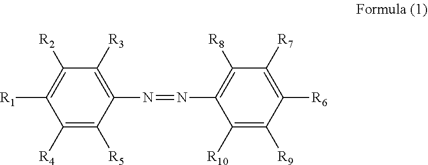
[0070]For example, as in the following Reaction Scheme A, 4-aminophenol is reacted with sodium nitrite under cooling to form a diazonium salt. This is reacted with o-cresol to synthesize intermediate A (first step), and then n-bromohexane is allowed to react with the intermediate A (second step). Thus, the above azobenzene derivative (1) may be obtained.

synthetic example 2

[0071]Synthesis of Azobenzene Derivative (4)

[0072]As indicated in the following Reaction Scheme B, the azobenzene derivative (4) may be obtained by changing o-cresol and n-bromohexane to 2-bromophenol and n-bromododecane respectively.

synthetic example 3

[0073]Synthesis of Azobenzene Derivative (5)

[0074]As indicated in the following reaction formula C, an azobenzene derivative compound (5) may be obtained by reacting an azobenzene derivative compound (4) with methanol in the presence of a Pd catalyst and a base.


PUM

PropertyMeasurementUnit
temperatureaaaaaaaaaa
melting point Tmaaaaaaaaaa
wavelengthaaaaaaaaaa

Abstract

Provided is an electrostatic image developing toner including toner particles containing a light phase transition material that change from a solid state to a liquid state by light irradiation and a binder resin, wherein ΔH1 (J/g) is 0.1 or more, provided that ΔH1 (J/g) is an endothermic amount based on a melting peak derived from the light phase transition material in a first temperature raising process of raising a temperature from 25 to 200° C., the endothermic amount being obtained from a DSC curve measured by differential scanning calorimtry to the electrostatic image developing toner.

Description

CROSS-REFERENCE TO RELATED APPLICATIONS[0001]The entire disclosure of Japanese Patent Application No. 2019-027040 filed on Feb. 19, 2019 is incorporated herein by reference in its entirety.BACKGROUND1. Technological Field[0002]The present invention relates to an electrostatic image developing toner and an image forming method. More particularly, the present invention relates to an electrostatic image developing toner and an image forming method capable of forming a toner image having high image strength in a fixing method by light irradiation.2. Description of the Related Art[0003]In the past, it was known an electrophotographic image forming apparatus for forming an image. In this method, an electrostatic latent image formed on a photoreceptor is developed with a toner to form a toner image, the formed toner image is transferred to a sheet, and the transferred toner image is heated and fixed, and an image is formed on the sheet. In such an image forming apparatus, in order to fix a...

Claims


Application Information

Patent Timeline
Patent Type & Authority Applications(United States)
IPC IPC(8): G03G9/087
CPCG03G9/08795G03G9/08797G03G9/08G03G9/087
Inventor TAKAHASHI, SEIJIROSUGAMA, KOUJIHORIGUCHI, HARUOKUSANO, YUKIKOSHIBATA, TOYOKO
Owner KONICA MINOLTA INC
Why Eureka
Try Eureka