
Comprehensive model-based method for gantry robot calibration via a dual camera vision system

a dual camera vision and gantry technology, applied in the direction of manipulators, program-controlled manipulators, manufacturing tools, etc., can solve the problems of unfavorable human labor in picking and placing components, lack of mathematical models to consider misalignment and scaling of gantry, etc., to achieve sufficient accuracy, fast and affordable methods, and reduce commissioning time

Inactive Publication Date: 2020-08-20
INTUNE PROD LLC
View PDF3 Cites 8 Cited by
  • Summary
  • Abstract
  • Description
  • Claims
  • Application Information

AI Technical Summary

Benefits of technology

The patent describes a way to calibrate a gantry system and a tool using a machine vision system. This method is accurate, fast, and affordable, and it can significantly reduce the time it takes to set up the system.

Problems solved by technology

These robots can be used in manufacturing of products such as medical devices, smart gadget, etc. with small components which picking and placing of those components are undesirable for human labor.
This approach does not establish a mathematical model to consider misalignments and scaling of the gantry system, camera installation error, tool misalignment in the system.

Method used


Image

  • Comprehensive model-based method for gantry robot calibration via a dual camera vision system
  • Comprehensive model-based method for gantry robot calibration via a dual camera vision system
  • Comprehensive model-based method for gantry robot calibration via a dual camera vision system

Examples


Embodiment Construction

Gantry Robot

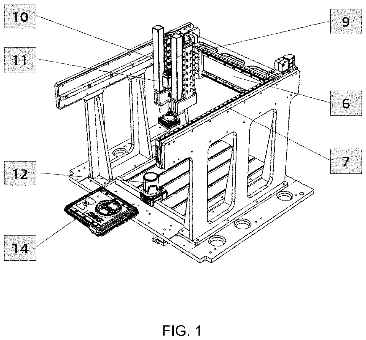
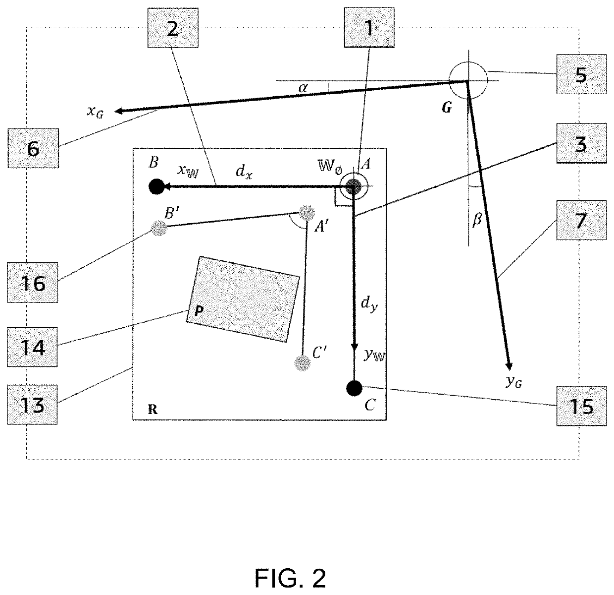
[0024]The close-up perspective view of gantry robotic system which is designed for assembling of products with tight tolerances in micrometer-level accuracy is illustrated in FIG. 1. It is assumed that the axes of the gantry robot have angular misalignment α and β radians with respect to the world coordinate system in the horizontal plane. Moreover, the axes are scaled by Sx,Sy in x-axis and y-axis, respectively.

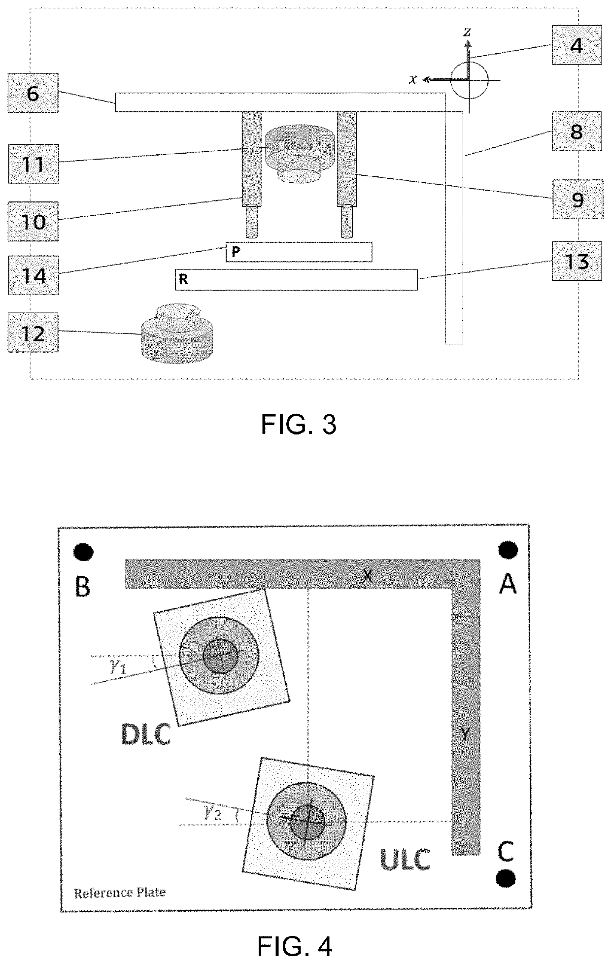
[0025]In the following, various embodiments of the invention will be described in detail. Such details are included to facilitate understanding and implementing of the invention. In order to find the above-mentioned unknown parameters in gantry robot, multiple coordinate systems including {C}, {G″}, {G′}, {G} and {W} are established. The coordinate {C} is camera coordinate system which is established at the center of camera with perfectly perpendicular X-Y axes; the coordinate {G} is gantry robot coordinate system; {W} is world coordinate system, and coordinates ...


PUM


Abstract

A comprehensive model-based mathematical method for calibration of a gantry robot and a tool via a dual camera vision system may employ an automatic calibration process that includes: (i) Camera Internal and External Calibration (ULC and DLC), (ii) Camera Installation, (iii) Robot Workspace Calibration, and (iv) Tool Calibration. The method may provide an accurate, fast and affordable method for robot calibration which may significantly reduce the commissioning time, such that the time-consuming, cumbersome, conventional trial-and-error method may be reduced to a time-efficient automatic procedure with no human interference.

Description

[0001]The present application claims the benefit of U.S. Provisional Patent Application No. 62 / 805,563, filed Feb. 14, 2019, which is hereby incorporated by reference in its entirety.FIELD OF THE INVENTION[0002]This manuscript focuses on a comprehensive model-based mathematical method for calibration of the gantry robot via dual camera vision system. We assume the axes of gantry system have angular misalignment in the horizontal plane i.e. the axes are not perfectly perpendicular to each other. Moreover, the axes are linearly scaled in X-axis and Y-axis with unknown scaling factor. Also, we assume the upward looking camera (ULC) and downward looking camera (DLC) are installed with minute angles on the gantry system. We presume the axes of camera view are perpendicular to each other but they are not perfectly aligned with the XY axes of the reference plate. It is also assumed that the tooling system is installed with some misalignment on X-axis of gantry system such that the tool axi...

Claims


Application Information

Patent Timeline
Patent Type & Authority Applications(United States)
IPC IPC(8): B25J9/16
CPCB25J19/023B25J9/1697B25J9/1692B25J9/026
Inventor GHOBADI, MOSTAFAALAMDARI, ALIAKBAR
Owner INTUNE PROD LLC
Learn More