Oil pulse unit of a pneumatic tool

a pneumatic tool and oil pulse technology, applied in the direction of wrenches, power driven tools, screwdrivers, etc., can solve the problem that the output shaft b>90/b> cannot provide enough torque to fasten the fixing elements

Inactive Publication Date: 2020-08-20
AIRBOSS AIR TOOLS CO LTD
View PDF0 Cites 2 Cited by
  • Summary
  • Abstract
  • Description
  • Claims
  • Application Information

AI Technical Summary

Benefits of technology

[0006]The main objective of the present invention is to provide an oil pulse unit of a pneumatic tool that can adjust the pressure of the hydraulic oil filled within, and can maintain the torque outputted.

Problems solved by technology

However, as shown in FIG. 10, as the operating time increases, the hydraulic oil flows within the oil pulse unit 80 repeatedly and therefore causes friction.
In that case, the output shaft 90 cannot provide enough torque to fasten the fixing elements.

Method used


Image

  • Oil pulse unit of a pneumatic tool
  • Oil pulse unit of a pneumatic tool
  • Oil pulse unit of a pneumatic tool

Examples


Embodiment Construction

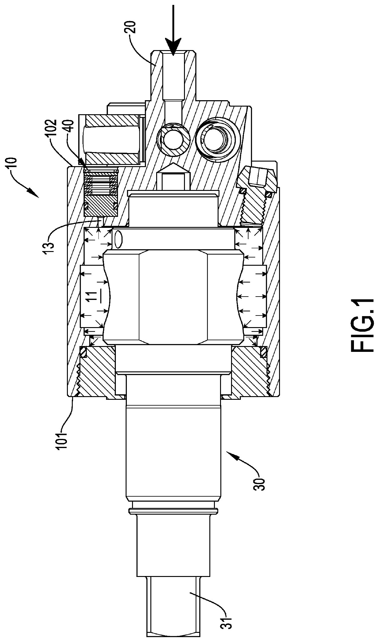
[0019]With reference to FIG. 1, an oil pulse unit of a pneumatic tool in accordance with the present invention comprises a cylinder 10, an input shaft 20, an output shaft 30, and a pressure-relief valve 40. The input shaft 20 is disposed on the cylinder 10. The output shaft 30 and the pressure-relief valve40 are mounted with the cylinder 10.

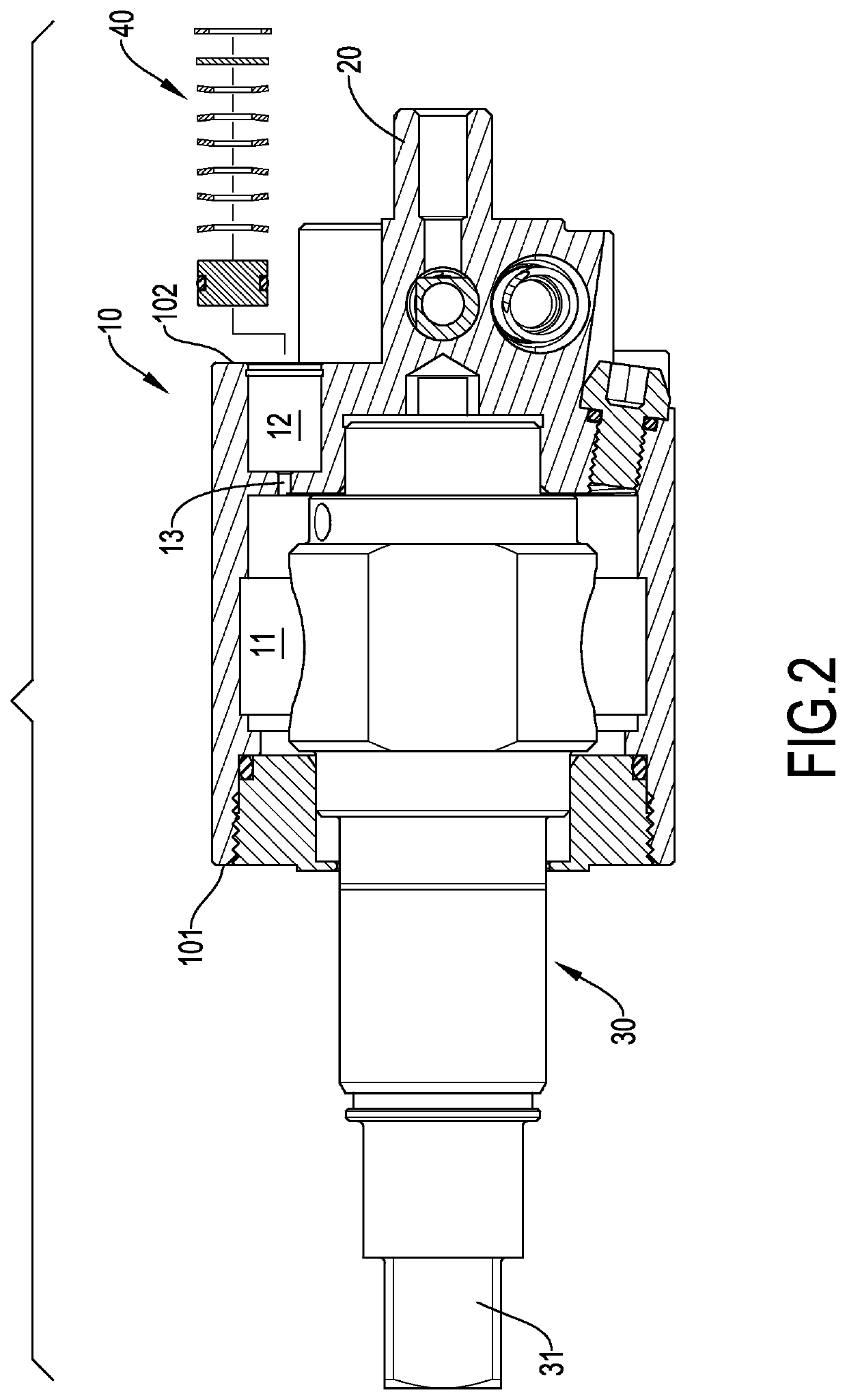
[0020]With reference to FIGS. 1 and 2, the cylinder 10 has an axial direction, a first end 101, a second end 102, a hydraulic oil chamber 11, a pressure-relief chamber 12, and a communicating channel 13. The first end 101 and the second end 102 are disposed oppositely on the cylinder 10 along the axial direction. The hydraulic oil chamber 11 is formed from the first end 101 of the cylinder 10 toward the second end 102 of the cylinder 10. The hydraulic oil chamber 11 is filled with hydraulic oil. The pressure-relief chamber 12 is formed from the second end 102 of the cylinder 10 toward the first end 101 of the cylinder 10. The pressure-relief cham...


PUM


Abstract

An oil pulse unit has a cylinder, an output shaft, and a pressure-relief valve. The cylinder has a hydraulic oil chamber, a pressure-relief chamber and a communicating channel. The communicating channel is formed in the cylinder between the hydraulic oil chamber and the pressure-relief chamber, and communicates with the hydraulic oil chamber and the pressure-relief chamber. The output shaft is mounted with the cylinder and extends into the hydraulic oil chamber. The pressure-relief valve is mounted in the pressure-relief chamber and has a piston, a seal ring, an elastic element, and a retaining ring. The seal ring is sleeved on the piston, and abuts against the piston and the pressure-relief chamber. The elastic element has a first end and a second end. The elastic element abuts against the piston. The retaining ring is embedded in the pressure-relief chamber and abuts against the elastic element.

Description

BACKGROUND OF THE INVENTION1. Field of the Invention[0001]The present invention relates to a structure of a pneumatic tool propelled by pressure of fluid, and more particularly to an oil pulse unit of a pneumatic tool that can adjust the pressure of the hydraulic oil filled within, and can maintain the torque outputted.2. Description of Related Art[0002]A pneumatic tool is a power tool driven by compressed air. Users can assemble or disassemble elements labor-savingly and quickly by the pneumatic tools. Conventional pneumatic tools can be roughly divided into two kinds. The first kind of the conventional pneumatic tool comprises a rotor, an impact assembly, and an output shaft. The rotor is mounted in the conventional pneumatic tool and is driven to rotate by compressed air. The rotor propels the impact assembly. Then the impact assembly impacts the output shaft to fasten fixing elements.[0003]With reference to FIGS. 8 and 9, the second kind of the conventional pneumatic tool compri...

Claims


Application Information

Patent Timeline
Patent Type & Authority Applications(United States)
IPC IPC(8): B25B21/02B25F5/00B25B23/145B25B23/14
CPCB25B23/1453B25B23/1405B25B21/02B25F5/005B25B21/00B25B23/145
Inventor CHANG, HSIN-HE
Owner AIRBOSS AIR TOOLS CO LTD
Why Eureka
Try Eureka