Electro-mechanical resuscitating apparatus

a resuscitation apparatus and electromechanical technology, applied in the field of life support medical devices, can solve the problems of untrained persons, unsafe rate of pressure and frequency for patients, and low cost and skill requirements, and achieve the effects of reducing costs and skill requirements, reducing wear and tear, and reducing risk

Active Publication Date: 2020-08-20
BIODESIGN INNOVATION LABS PTE LTD
View PDF0 Cites 3 Cited by
  • Summary
  • Abstract
  • Description
  • Claims
  • Application Information

AI Technical Summary

Benefits of technology

[0006]The present invention relates to a Mechanical Ventilation device which delivers Intermittent Positive Pressure Ventilation (IPPV) by mechanically compressing the Ambu bag, and essentially automating the process of bagging. The frequency of ventilation can be set by a trained medical professional and oxygen supplementation can also be given. The mechanical motion of the Ambu compression mechanism is synthesised to deliver end values of pressure and frequency in-par with that delivered when given by a trained and experienced medical professional. In effect, the device simulates the effects of hand compression from a trained professional during ventilation.In an embodiment, an electro-mechanical resuscitating apparatus for controlling expansion and compression of an Ambu bag is provided. The apparatus includes a first supporting arm and a second supporting arm 104, wherein each of the first supporting arm 102 and second supporting arm 104 includes a coupling end and a placement end respectively, wherein a length of the each supporting arm between the coupling end and the placement end conforms to at least a portion of an outer surface area of the Ambu bag; a first coupling arm 110 and a second coupling arm 112 connected to each other through a plurality of connecting elements while maintaining a predetermined distance across respective lengths, wherein the first supporting arm is rotatably fixed at a first end between the first coupling arm 110 and second coupling arm 112 and the second supporting arm 104 is rotatably fixed at a second end 116 between the first coupling arm 110 and second coupling arm 112; a first driving mechanism and a second driving mechanism coupled to a first shaft 118 and a second shaft 120 respectively, wherein a front end of the first shaft 118 is coupled to the coupling end of the first supporting arm and a front end of the second shaft 120 is coupled to the coupling end of the second supporting arm 104, and a controller communicatively coupled to the first driving mechanism and the second driving mechanism, wherein the controller is configured to control the speed and direction of movement of the first shaft 118 and the second shaft 120 via the first driving mechanism and the second driving mechanism, wherein an actuation of the first shaft 118 and second shaft 120 in a first direction enables movement of the placement ends of the respective first supporting arm and the second supporting arm 104 against surface of the Ambu bag causing compression of the Ambu bag, wherein an actuation of the first shaft 118 and second shaft 120 in a second direction enables movement of the placement ends of the first supporting arm and the second supporting arm 104 to retract causing retraction of the Ambu bag.
[0007]It is an object of the present invention to provide mechanism that uses existing Ambu bag for the compression, and provides a simpler mechanism to automate the process of hand ventilation and will hence keep the costs and skill requirement low.
[0008]It is an object of the present invention to provide mechanism that is easy to manufacture and maintain and cause minimal damage and wear and tear of the Ambu bag.

Problems solved by technology

In developing and under-developed countries, it is used for long durations mainly due to unavailability of an ICU bed with a ventilator or absence of a portable transport-ventilator.
One major issue with this practice is that untrained persons, usually the patients care-taker is asked to do the bagging due to lack of trained staff.
This results in the patient being ventilated at suboptimal and often unsafe rates of pressure and frequency for very long durations at the hands of the caretaker.

Method used


Image

  • Electro-mechanical resuscitating apparatus
  • Electro-mechanical resuscitating apparatus
  • Electro-mechanical resuscitating apparatus

Examples


Embodiment Construction

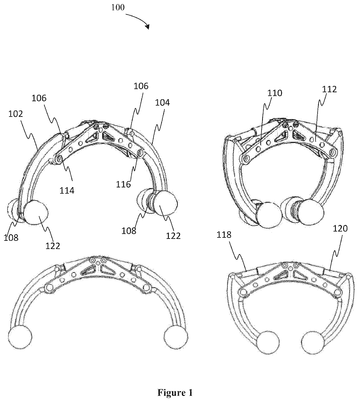
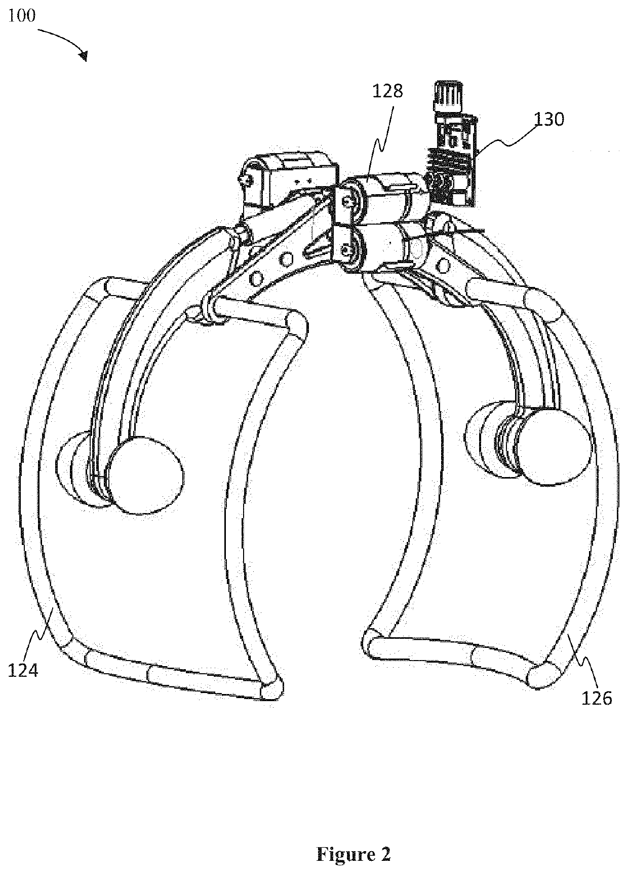
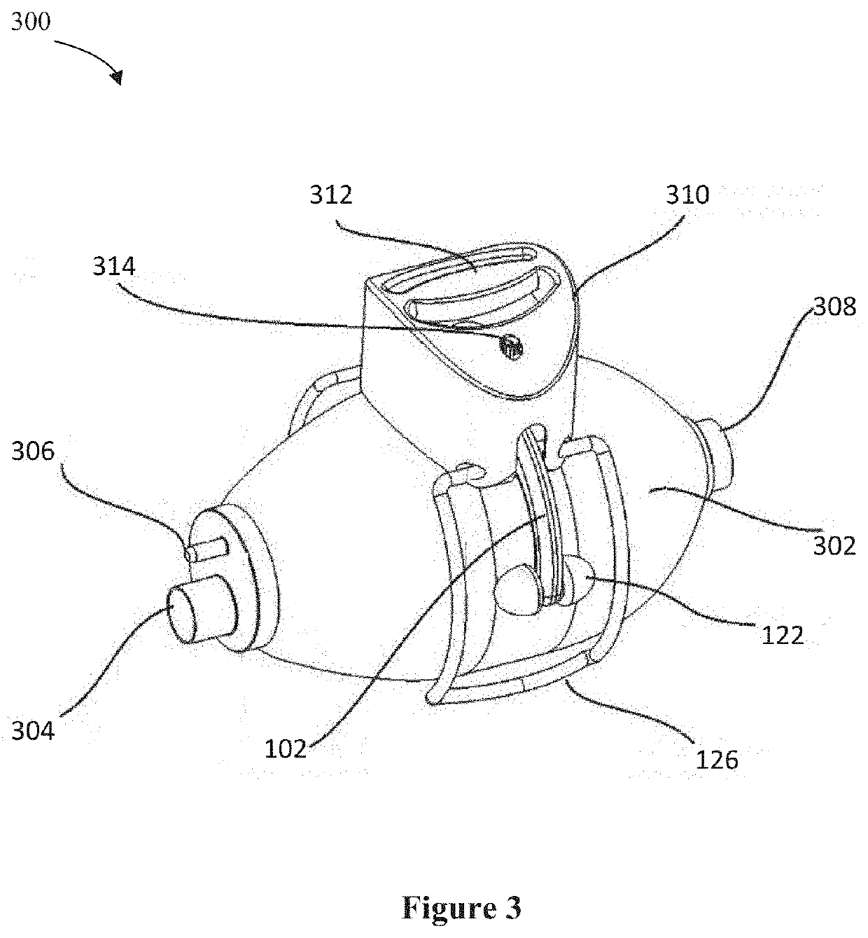
[0017]For the purpose of promoting an understanding of the principles of the invention, reference will now be made to the embodiment illustrated in the drawings and specific language will be used to describe the same. It will nevertheless be understood that no limitation of the scope of the invention is thereby intended, such alterations and further modifications in the illustrated system, and such further applications of the principles of the invention as illustrated therein being contemplated as would normally occur to one skilled in the art to which the invention relates.

[0018]In this specification, the words “print”, “printed” and “printing” are used to refer to the making of an original document regardless of the techniques used, and the words “copy” and “copying” to refer to making copies from an original.

[0019]It will be understood by those skilled in the art that the foregoing general description and the following detailed description are exemplary and explanatory of the inv...


PUM


Abstract

The present invention is a mechanical ventilation device which delivers intermittent positive pressure ventilation by compressing AMBU. As the device uses existing AMBU for the ventilation, it is intended to automate the process of hand ventilation and will hence keep the costs and skill requirement low. Due to usage of the AMBU and simple mechanics, it is easy to manufacture and maintain the device.

Description

FIELD OF THE INVENTION[0001]The present invention relates generally to the life-support Medical device for mechanical ventilation and particularly, relates to an electro-mechanical resuscitating apparatus for controlling expansion and compression of an Ambu bag.BACKGROUND[0002]Manual resuscitators using self-inflating bags or Ambu bags are well recognized in the prior art. The AMBU-bags or self-inflating bags are hand-held devices and are in wide spread use in medical and emergency treatment of patients and commonly used to provide positive pressure ventilation to patients who are not breathing or not breathing adequately. They are designed for manually squeezing, such as by a doctor, nurse, orderly, EMT or other medical service provider. Their usage includes, for example, respiration a patient in the field and / or during transport to a hospital.[0003]AMBU-bags or self-inflating bags are primarily used for keeping a patient respirated during movement from one location to another or d...

Claims


Application Information

Patent Timeline
Patent Type & Authority Applications(United States)
IPC IPC(8): A61M16/00A61M16/20
CPCA61M2016/0033A61M16/0084A61M2205/8206A61M16/209A61M2202/0208A61M2205/07A61M16/022A61M16/0051A61M16/0003A61M16/0081A61M2205/10A61M16/00
Inventor PASUPULETI, GAUTHAMPASUPULETI, ADITHYAMOHAN, ROSHAN
Owner BIODESIGN INNOVATION LABS PTE LTD
Why Eureka
Try Eureka