
Ophthalmic imaging system

a technology of ophthalmic imaging and optical path, applied in the field of ophthalmic imaging system, can solve the problems of inconvenient operation, difficult to maintain the proper functions of the internal fixation target in both modes, and compromise the image quality of the fixation optical path, so as to improve the achievable field of view and imaging resolution, the effect of high repeatability precision

Active Publication Date: 2020-08-06
SVISION IMAGING LTD
View PDF0 Cites 1 Cited by
  • Summary
  • Abstract
  • Description
  • Claims
  • Application Information

AI Technical Summary

Benefits of technology

The present invention is an ophthalmic imaging system that can switch between anterior segment and retina imaging modes using a lens group. The system is designed to be telecentric or near telecentric for both segments, improving field of view and resolution. The switching of imaging modes does not affect other optical paths of the system. The lens group switching device is compact, reliable, and easy to assemble, and can be used in other optical instruments and devices.

Problems solved by technology

However, this method has the problem that the imaging quality of the fixation optical path is compromised.
External switching methods, such as Patent US2008 / 0106696A1, require manual operation of users, which is inconvenient to operate and difficult to maintain proper functions of the internal fixation target in both modes.
In those approaches, the available field of view is limited.
It can hardly support telecentric imaging and thus limits the capability of quantitative measurement.

Method used


Image

  • Ophthalmic imaging system
  • Ophthalmic imaging system
  • Ophthalmic imaging system

Examples


embodiment 1

[0093]As shown in FIG. 7, in the ophthalmic imaging system, the OCT imaging module, the SLO imaging module, the pupil camera module and the fixation target module share one ocular lens. The working distance L1A between the ocular lens and the human eye to be tested can be adjusted to facilitate focusing of the pupil camera module. The distance L2A from the back of the ocular lens to the first dichroic mirror DM01 can be adjusted to compensate the refractive difference of human eyes for up to + / −20 diopters.

[0094]In the ophthalmic imaging system, as shown in FIG. 7, the OCT imaging module and the SLO imaging module are both located on the same side of a line where a visual axis of the eye is located, and the pupil camera module is on the opposite side. The advantage of the present embodiment is that the SLO imaging module passes through only one dichroic mirror, and results the lowest impact on the image quality.

[0095]In the present embodiment, optical path division between the OCT i...

embodiment 2

[0099]As shown in FIG. 8, in the ophthalmic imaging system, the OCT imaging module, the SLO imaging module, the pupil camera module and the fixation target module share one ocular lens. The working distance L1B between the ocular lens and the human eye to be tested can be adjusted to facilitate the focusing of the anterior segment imaging system. The distance L2B from the back of the ocular lens to the first dichroic mirror DM01 can be adjusted to compensate for the refractive difference of human eyes.

[0100]In the ophthalmic imaging system, as shown in FIG. 8, the OCT imaging module, the fixation module and the pupil camera module are all located on the same side of the line where the visual axis of the eye. The DM02B is a dichroic mirror of long wave transmission and short wave reflection and more readily available as a catalog product than the opposite. In the present embodiment, optical path division between the OCT imaging module and other functional modules is achieved by a dic...


PUM


Abstract

An ophthalmic imaging system including an ocular lens and an optical coherence tomography (OCT) imaging module is provided. The OCT imaging module is able to image both retina and anterior segment of eyes by switching a lens group into and out of the OCT light path. The OCT imaging module includes a retina imaging mode and an anterior segment imaging mode. In the retina imaging mode, there exists an intermediate image plane located between the ocular lens and the OCT imaging module. From the retina imaging mode, anterior segment imaging is achieved by inserting a switching lens group into the optical path inside the OCT imaging module or replacing the whole OCT imaging module of the retina mode, wherein, after the insertion, there exist a new intermediate image plane located inside the OCT imaging module and a conjugate of the entrance pupil of the OCT imaging module located between the ocular lens and the OCT imaging module.

Description

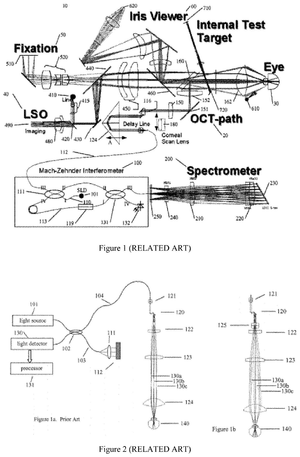
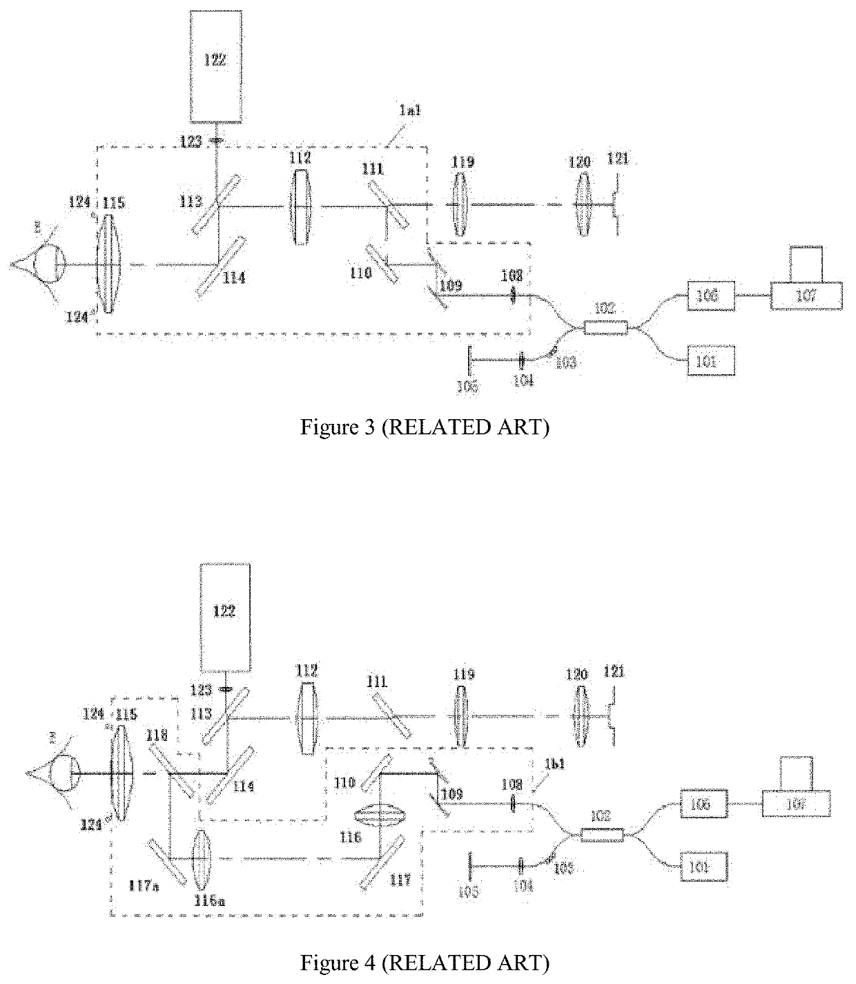
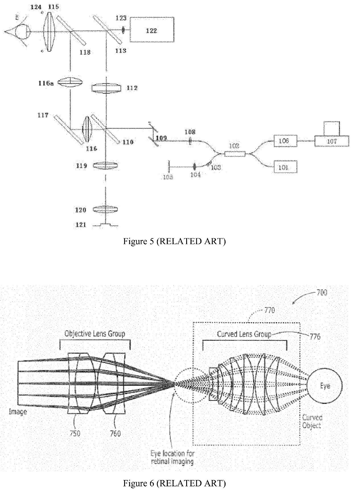
CROSS-REFERENCE TO RELATED APPLICATION[0001]This application is a continuation in part of international PCT application serial no. PCT / CN2018 / 110791, filed on Oct. 18, 2018, which claims the priority benefit of China application no. 201710991897.2, filed on Oct. 20, 2017, China application no. 201810799715.6, filed on Jul. 18, 2018 and China application no. 201821150335.1, filed on Jul. 18, 2018. The entirety of each of the above-mentioned patent applications is hereby incorporated by reference herein and made a part of this specification.BACKGROUNDTechnical Field[0002]The present invention relates to an ophthalmic imaging system.Description of Related Art[0003]Optical coherence tomography (OCT) technology has the characteristics of high resolution, high imaging speed and non-invasion. Ophthalmic imaging is one of the most popular applications of the OCT technology.[0004]Please refer to FIG. 1, U.S. Pat. No. 8,427,654 introduces an optical design of an ophthalmic imaging apparatus i...

Claims


Application Information

Patent Timeline
IPC IPC(8): A61B3/10G01B9/02A61B3/12
CPCG01B9/02091A61B3/1225A61B3/102A61B3/1025
Inventor WU, HENGPENG, XIANZHAOCHENG, NANFAN
Owner SVISION IMAGING LTD
Learn More