
Systems and methods for leak monitoring via measurement of optical absorption using tailored reflector installments

a technology of optical absorption and leak monitoring, which is applied in the direction of fluid tightness measurement, instruments, mechanical equipment, etc., can solve the problems of difficult quantification of gas leakage, limited spatial coverage of conventional point and line detectors for gas detection, and create both safety and environmental hazards, so as to achieve rapid and accurate detection, localization, and quantification

Active Publication Date: 2020-07-30
MULTISENSOR SCI INC
View PDF21 Cites 6 Cited by
  • Summary
  • Abstract
  • Description
  • Claims
  • Application Information

AI Technical Summary

Benefits of technology

The patent describes a new technology for detecting gas leaks and emissions. This technology uses infrared technology to monitor the spectral bands of hydrocarbon compounds and carbon dioxide. The technology has the advantages of being cost-effective and not needing specialized detectors. It can be used in a wide range of environments and can be easily installed at different locations. By using this technology, gas leak detection can be done quickly and effectively over large areas.

Problems solved by technology

Natural gas leaks create both safety and environmental hazards, and occur along the entire gas supply chain from the well to the street (so-called upstream, midstream, and downstream sectors).
Other hydrocarbons found in natural gas, as well as vapors emanating from liquids separated from gas and oil, include ethane, propane, butane, pentane, hexane, octane, ethylene and heavier hydrocarbons, which form volatile organic compounds that generate smog which is a health hazard.
Conventional point and line detectors for gases have limited spatial coverage for detection as they rely on wind or air movements to transport the gas towards the point or line detector.
Detection, localization, and quantification of gas leaks is challenging, since leak monitoring and / or inspection typically need to be performed over wide areas, and from a safe and practical standoff distance.

Method used


Image

  • Systems and methods for leak monitoring via measurement of optical absorption using tailored reflector installments
  • Systems and methods for leak monitoring via measurement of optical absorption using tailored reflector installments
  • Systems and methods for leak monitoring via measurement of optical absorption using tailored reflector installments

Examples


example 1

tion of Gas Detection Via a Three Sided Optical Curtain

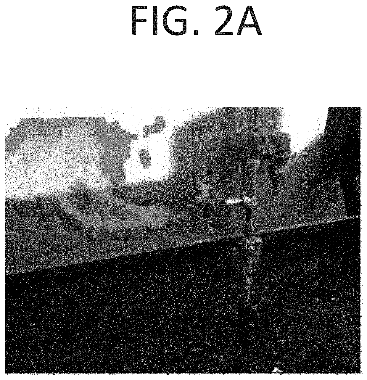
[0177]This example demonstrates detection of gas via a three sided optical curtain. FIG. 15A shows a visible camera image of a scene comprising a pipe 1502 releasing gas and a retro-reflector installment used to create the optical curtain. The pipe 1502 is a 2 inch vent pipe leaking at a rate of approximately 20 standard cube feet per hour (SCFH). The reflector installment includes a frame 1506 having retroreflective surfaces mounted behind the pipe. 3M High Intensity Prismatic Grade Reflective Sheeting 3930 is used as the retro-reflective surface. A scanning optical sensor and illuminator directs light to locations about the retro-reflective frame 1506 and detects light reflected back to the detector, thereby forming a three-sided optical curtain. The visible camera image of FIG. 15A is taken from the vantage point of the optical sensor and illuminator, which are situated a distance of about 5 meters from the pipe 1502 and 7 m ...

example 2

tion of Gas Detection at 20 Meters

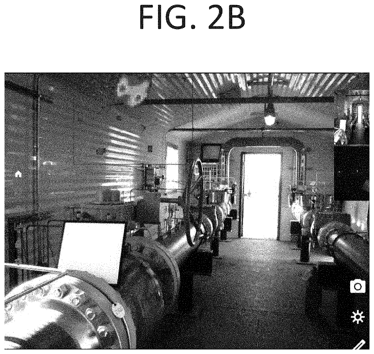
[0178]Example 2 demonstrates gas detection at a distance of 20 meters using 3M 3930 retro-reflectors positioned behind a gas leak source. FIG. 16 shows a visible camera image of a room with an absorption image overlaid showing levels of absorption in false color. As shown in the figure, leaking gas can be seen in a region 1602a at the back of the room (inside a fume hood). An expanded view 1602b of the region shows the detected gas leak in greater detail. Accordingly, this example shows how a single, or small number of strategically positioned retro-reflectors can be used to detect gas leaks at tens of meters using a scanning multispectral optical sensor and co-located scanning (broadband) illuminator.

example 3

nning Over a Wide Field of View

[0179]This example demonstrates how the tailored retro-reflector installment approaches described herein can be used to allow for large fields of view to be scanned rapidly. An example is an installation using discontinuous reflectors at an oil well as depicted in FIG. 18. Such a well may typically include one or several pump jacks, measurement equipment, a separator, and tanks. A retro-reflector panel or retro-reflector stripe may be each placed behind pump jack, a separator (or, for example, in the case of an enclosed separator behind a relief vent, on top of such separator enclosure), behind measurement equipment, and behind any pressure relief valve or hatch on top of a tank. For example, in FIG. 18, four separated locations to be monitored: storage tanks (pressure relief valves and thief hatches), a compressor shed (roof vents), a separator tank roof (vent), and pump jacks are shown. It is noted that in an installation the retro-reflector might be...


PUM

PropertyMeasurementUnit
angle of incidenceaaaaaaaaaa
reflectivityaaaaaaaaaa
angleaaaaaaaaaa

Abstract

Presented herein are systems and methods directed to a multispectral absorption-based imaging approach that provides for rapid and accurate detection, localization, and quantification of gas emission from within a site to be monitored. The imaging technology described herein utilizes an optical sensor and broadband illumination in combination with specialized reflector installments mounted about the site. The optical sensor detects light (e.g., reflected) from a plurality of sampled locations along the reflector installment, for example by imaging multiple sampled locations at a time and / or scanning an instantaneous field of view (ifov) of the optical sensor. Lines-of-sight from the optical sensor to sampled locations along the reflector installment sweep out an “optical curtain” partially enclosing and / or forming a boundary near various assets to be monitored. Optical absorption signatures from leaking gas crossing the optical curtain can be used to detect, localize, and obtain quantitative measures characterizing the leak.

Description

CROSS-REFERENCE TO RELATED APPLICATIONS[0001]This application claims priority to and benefit of U.S. Provisional Patent Application No. 62 / 797,065, entitled “Systems and Methods for Leak Monitoring via Measurement of Optical Absorption Using Tailored Reflector Installments” and filed Jan. 25, 2019, the content of which is hereby incorporated by reference herein in its entirety.FIELD OF THE INVENTION[0002]This invention relates generally to methods, systems, and apparatus for detection of emission of gas, e.g., methane, other hydrocarbons, carbon dioxide or ammonia, via measurement of optical absorption and tailored reflector installments. In particular, in certain embodiments, this invention relates to methods, systems, and apparatus for detection, localization and quantification of emission of multiple gases from within a site to be monitored via a scanning illuminator co-located with an optical sensor in combination with the tailored reflector installment.BACKGROUND OF THE INVENTI...

Claims


Application Information

Patent Timeline
Patent Type & Authority Applications(United States)
IPC IPC(8): G01N21/359G01N21/3504
CPCG01N2201/0636G01N2201/061G01N21/359G01N21/3504G01M3/38F17D5/005F17D5/06G01M3/202G01N33/0036
Inventor WAXMAN, ALLEN M.BOKAEMPER, STEFANJONES, TERRENCE K.ROBOTHAM, CLAUDE V.
Owner MULTISENSOR SCI INC
Learn More