Eureka AIR delivers breakthrough ideas for toughest innovation challenges, trusted by R&D personnel around the world.

Drive circuit for a variable speed fan motor

a technology of variable speed fan motor and drive circuit, which is applied in the control of dc and ac dynamo-electric motors, instruments, lighting and heating apparatus, etc., can solve the problems of system hardware and software, and significantly increase the cost of cooling systems

Active Publication Date: 2020-07-30
REGAL BELOIT AMERICA
View PDF0 Cites 1 Cited by
  • Summary
  • Abstract
  • Description
  • Claims
  • Application Information

AI Technical Summary

Benefits of technology

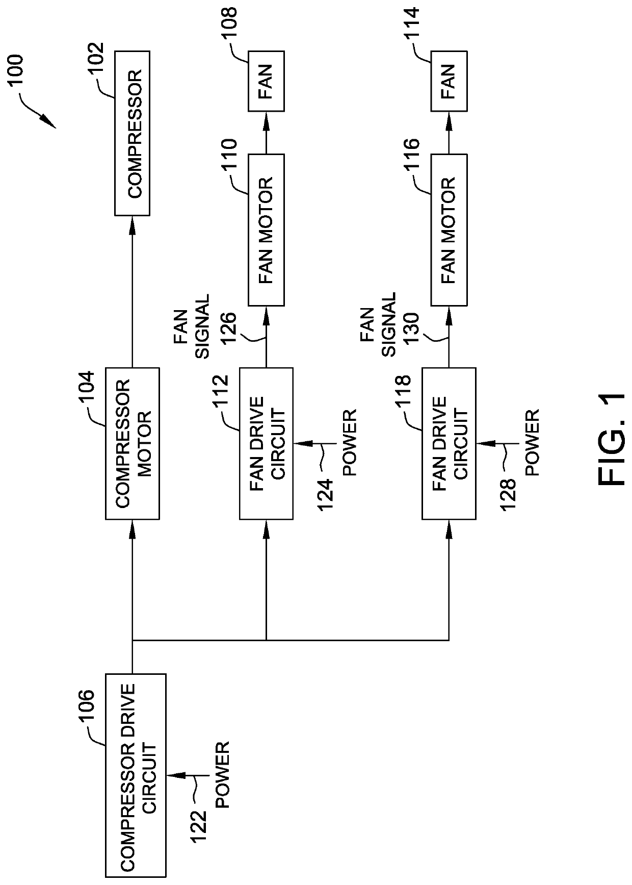
The patent describes a fan drive circuit for a variable speed fan motor in a cooling system. The circuit includes an inverter that supplies a current signal to stator windings of the fan motor. The circuit also includes a frequency detection circuit that detects the first frequency of a compressor current signal and sends a frequency signal to a digital signal processor (DSP). The DSP selects a second frequency based on the first frequency and sends control signals to the inverter to supply current to the fan stator windings at the second frequency. The technical effect of this patent is to provide a variable speed fan motor in a cooling system that can automatically adjust its speed based on the frequency of the compressor current signal, thus improving the efficiency and performance of the cooling system.

Problems solved by technology

Generally, fan motors used in cooling systems lack hardware and software for operating at a variable speed, and adding such hardware or software to a cooling system to facilitate variable speed operation may significantly increase the cost of the cooling system.

Method used


Image

  • Drive circuit for a variable speed fan motor
  • Drive circuit for a variable speed fan motor
  • Drive circuit for a variable speed fan motor

Examples


Embodiment Construction

[0010]The embodiments described herein provide a variable speed fan motor for use in a cooling system, such as, for example, a commercial refrigerator. The embodiments described herein enable the operation of fan motors at variable speeds in coordination with a compressor motor. More specifically, the fan motors described herein are configured to detect a frequency of a current signal (or voltage signal) supplied to stator windings of the compressor motor and determine a frequency at which to supply current (or voltage) to stator windings of the fan motor based on the detected frequency of the compressor current signal. Accordingly, the fan motor is controlled by the compressor current signal supplied to the stator windings of the compressor. Thus, the fan motor operates at a variable speed and coordinates that variable speed with the compressor motor without the need for additional hardware or software. For example, during periods of lower cooling demand, where the compressor motor...


PUM


Abstract

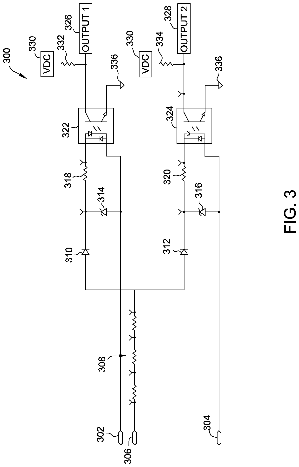
A fan drive circuit for a variable speed fan motor in a cooling system, includes an inverter configured to supply a current signal to stator windings of the variable speed fan motor, a frequency detection circuit coupled to an output stage of an inverter of a compressor motor of the cooling system and configured to detect a first frequency of a compressor current signal at the output stage of a variable speed compressor drive circuit and generate a frequency signal, and a digital signal processor (DSP) coupled to the inverter and the frequency detection circuit. The DSP is configured to receive the frequency signal corresponding to the first frequency from the frequency detection circuit, select a second frequency corresponding to the first frequency at which to operate the variable speed fan motor, and transmit control signals to the inverter to supply current to the stator windings at the second frequency.

Description

BACKGROUND[0001]The field of the disclosure relates generally to electric motors and cooling systems, and, more particularly, to a drive circuit for a variable speed fan motor.[0002]Cooling systems generally include a compressor, a condenser fan, and an evaporator fan, each powered by one or more electric motors. Greater energy efficiency can be achieved when the compressor uses a variable speed motor. Generally, fan motors used in cooling systems lack hardware and software for operating at a variable speed, and adding such hardware or software to a cooling system to facilitate variable speed operation may significantly increase the cost of the cooling system. It is desirable for cooling systems to have variable speed fan motors without the need for additional hardware or software, and without significant cost.BRIEF DESCRIPTION[0003]In one aspect, a fan drive circuit for a variable speed fan motor in a cooling system includes an inverter configured to supply a current signal to stat...

Claims


Application Information

Patent Timeline
IPC IPC(8): F25B49/02G05B17/02
CPCF25B49/025G05B17/02F25B2600/112F25B2700/151F25B2600/111F04D25/08F04D27/004H02P5/60H02P6/04H02P27/06F04D29/582F25B31/006F25B49/022F25B2600/021Y02B30/70
Inventor MULLIN, PAUL S.THOMPSON, DANIEL E.
Owner REGAL BELOIT AMERICA
Why Eureka
Eureka Blog
Learn More