
Air spring with integral intermediate chamber

Inactive Publication Date: 2020-07-30
HENDRICKSON USA L L C
View PDF0 Cites 3 Cited by
  • Summary
  • Abstract
  • Description
  • Claims
  • Application Information

AI Technical Summary

Benefits of technology

The present invention improves the connection between the piston and the continuous bellows of an air spring to prevent separation and air loss during rebound events. It also reduces the bellows volume to increase damping energy without limiting or obstructing travel of the air spring. The damping characteristics of the air spring are optimized to accommodate a broader range of loads and wheel motions and reduce operating constraints and frequency dependence. Additionally, the invention provides an intermediate chamber that prevents limitation or obstruction of fluid communication between the bellows chamber and intermediate chamber. Finally, the air spring maintains its damping energy during extreme jounce events.

Problems solved by technology

At these frequencies, the axle / suspension system is predisposed to move such that road inputs at these frequencies may result in a harmonic build-up of movement in the axle / suspension system that can potentially adversely affect the performance of the axle / suspension system.
Prior art air springs without damping characteristics, while adequately cushioning the heavy-duty vehicle cargo and occupant(s) during operation, have potential disadvantages, drawbacks, and limitations.
For example, the manner in which prior art air springs secure the bellows to the piston may potentially result in the bellows becoming dislodged or separated from the piston during rebound events.
More specifically, during an extreme rebound event, the bellows may become over-extended such that the bottom portion of the bellows may become unsecured from the piston.
Prior art non-damping air springs also provide little, if any, damping characteristics to the axle / suspension system.
However, these shock absorbers experience changes and limitations in their damping performance.
In particular, shock absorbers typically experience changes in performance characteristics over time as they wear, causing changes in the ride and handling characteristics of the heavy-duty vehicle that, in turn, may cause additional wear of the tires and other components of the axle / suspension system over time.
More particularly, these changes can potentially increase operational costs of the heavy-duty vehicle.
Thus, as payload is added or removed from the heavy-duty vehicle, the performance of the shock absorbers may potentially become non-optimal.
More specifically, shock absorbers are typically designed for the heaviest expected payload of the heavy-duty vehicle such that the axle / suspension system will become overdamped for lighter loads, potentially increasing wear on the tires and other components of the axle / suspension system.
Furthermore, shock absorbers are a service item of the axle / suspension system that require maintenance and / or replacement from time to time, resulting in increased maintenance and / or replacement costs of the axle / suspension system.
Shock absorbers also add varying degrees of complexity and weight to the axle / suspension system.
More particularly, because shock absorbers are relatively heavy, the shock absorbers add undesirable weight to the axle / suspension system, thereby reducing the amount of cargo that can be carried by the heavy-duty vehicle.
This pressure differential causes air to flow between the bellows and piston chamber through the opening(s) of the piston top plate causing damping to occur.
Prior art air springs with damping characteristics, while providing adequate damping to the axle / suspension system of the heavy-duty vehicle, have potential disadvantages, drawbacks, and limitations.
However, prior art damping air springs generally only provide peak damping characteristics for a single critical frequency range.
In addition, the structure and attachment of the bellows of prior art damping air springs can potentially cause changes in the damping energy of the air spring during jounce events or separation of the bellows from the piston during rebound events.
During a jounce event or under increased load, compression of the prior art damping air spring bellows typically increases the tension on the bellows material, potentially causing the bellows material to stretch radially and the bellows diameter to expand beyond a nominal diameter, increasing the volume of the bellows chamber, thereby decreasing the damping energy of the prior art air spring.
In addition, during an extreme rebound event, the bellows may become over-extended, such that the bottom portion of the bellows may potentially become unsecured from the piston, potentially causing air loss and / or damage to the prior art air spring and / or other components of the axle / suspension system.
Furthermore, prior art damping air springs with intermediate chambers generally require separate manufacturing and assembly of the intermediate chamber and air spring bellows.
The top plates of the intermediate chambers are generally large, and the support mechanisms are typically complex multi-component structures, increasing the weight, complexity, cost of materials and manufacturing, and difficulty of repair and / or replacement of the intermediate chamber.
However, the support mechanisms can potentially limit air flow within the piston chamber, obstruct air spring travel, cause damage to the piston, or require additional components.
Moreover, embedded support mechanisms for the intermediate chamber are difficult to optimize, potentially resulting in improper or non-optimal stiffness, restriction of air spring travel, or premature collapse of the intermediate chamber and loss of damping energy.
During jounce events, the bellows top plate may contact the top plate of the intermediate chamber, potentially obstructing the openings in the top plate of the intermediate chamber, thereby limiting or obstructing fluid flow between the bellows and intermediate chamber.

Method used


Image

  • Air spring with integral intermediate chamber
  • Air spring with integral intermediate chamber
  • Air spring with integral intermediate chamber

Examples


Embodiment Construction

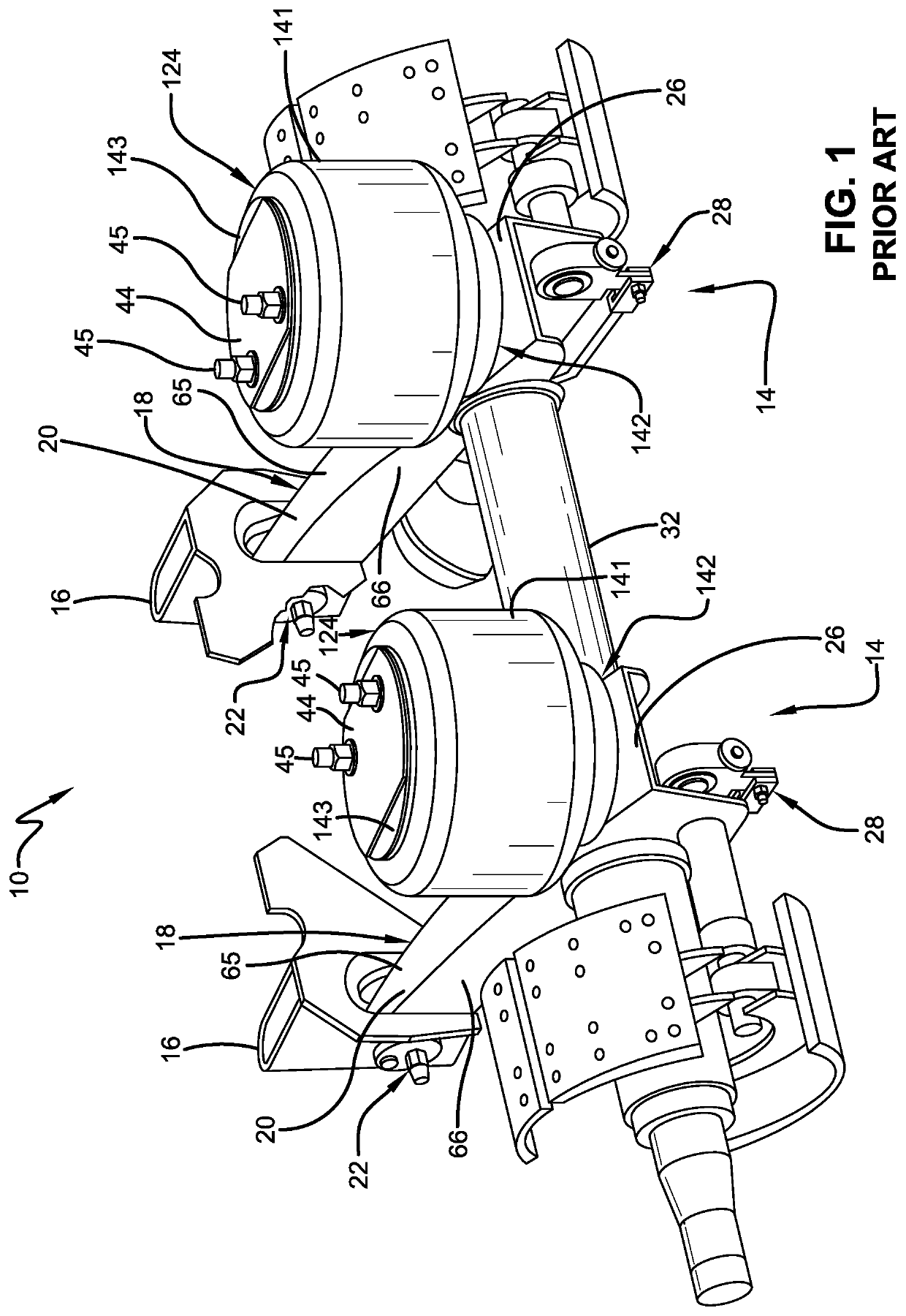
[0046]In order to better understand the environment in which the damping air spring of the present invention is utilized, a prior art non-damping air spring 124 (FIG.1) is shown incorporated into a prior art air-ride axle / suspension system 10. Prior art axle / suspension system 10 typically includes a pair of mirror-image suspension assemblies 14 mounted on a pair of longitudinally-extending spaced-apart main members (not shown) of a heavy-duty vehicle (not shown). Because suspension assemblies 14 are mirror-images of each other, for the sake of clarity and conciseness, only one of the suspension assemblies will be described below.

[0047]Suspension assembly 14 is pivotally connected to a hanger 16 via a beam 18. More specifically, beam 18 has a pair of sidewalls 66 and a top plate 65 formed in a generally upside-down integral U-shape with the open portion facing generally downwardly. A bottom plate (not shown) extends between and is attached to the lowermost ends of sidewalls 66 by any...


PUM


Abstract

An air spring for a heavy-duty vehicle axle / suspension system comprising a piston, a bellows, and an intermediate chamber integrally formed with the bellows. The bellows has an upper portion, a top plate, and a bellows chamber and is connected to the piston by a band, a bead-in-groove connection, and / or a bayonet connection. The upper portion is reinforced to prevent the bellows chamber from increasing in volume. The intermediate chamber has an optimally sized top plate and a support structure and extends from the piston into the bellows chamber. The intermediate top plate is formed with means for restricted fluid communication between the bellows chamber and the intermediate chamber. The means for restricted fluid communication is not obstructed when it contacts the bellows top plate during jounce events. The support structure is optimized in relation to the top plate.

Description

CROSS-REFERENCE TO RELATED APPLICATION[0001]This application claims the benefit of U.S. Provisional Patent Application No. 62 / 798,247, filed Jan. 29, 2019.BACKGROUND OF THE INVENTIONField of the Invention[0002]The present invention relates generally to the art of axle / suspension systems for heavy-duty vehicles. In particular, the invention relates to heavy-duty vehicle axle / suspension systems that utilize an air spring to cushion the ride of the heavy-duty vehicle. More particularly, the present invention is directed to an air spring with damping characteristics that includes a flexible continuous bellows that forms an upper bellows with a bellows chamber, a rolling portion, and an intermediate bellows, and is optionally mounted to the piston by a bayonet and / or bead-in-groove connection with smooth or textured sealing surface optionally secured together with a retaining band. The upper bellows includes a reinforced portion that prevents radial expansion of the bellows chamber, main...

Claims


Application Information

Patent Timeline
IPC IPC(8): B60G11/58F16F9/04
CPCB60G2206/8101B60G11/58B60G2202/15F16F2222/126F16F9/0472B60G2206/424B60G11/27B60G2202/152B60G13/10B60G15/12B60G17/0521B60G2202/242B60G2202/30B60G2204/45B60G2300/026B60G2500/10F16F9/049F16F9/05
Inventor DELORENZIS, DAMONZAWACKI, JEFF R.
Owner HENDRICKSON USA L L C
Learn More