
Enhanced drainage of failed glaucoma drainage device (GDD)

a drainage device and glaucoma technology, applied in the field of gdds, can solve the problems of gdd not providing sufficient drainage, human glaucoma drainage device (gdd) implants failing to moderate an acceptable intraocular pressure, and long-term inflammation risk

Pending Publication Date: 2020-07-23
UNIV OF FLORIDA RES FOUNDATION INC
View PDF4 Cites 0 Cited by
  • Summary
  • Abstract
  • Description
  • Claims
  • Application Information

AI Technical Summary

Benefits of technology

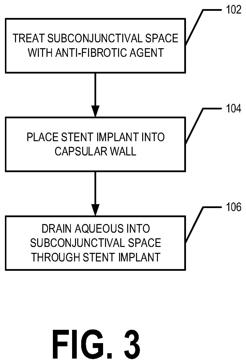
Example embodiments provide techniques for managing and resolving failed GDDs. These techniques require only a simple office or minor-operating room procedure. In an example embodiment, a failed GDD may be made to function again by placing and / or implanting a stent implant into the wall of the fibrous capsule to allow aqueous to flow through the stent into the subconjunctival space. The technical effect of this patent text is to provide a non-invasive and effective treatment for failed GDDs.

Problems solved by technology

Approximately 15-40% of human glaucoma drainage device (GDD) implants fail to moderate an acceptable intraocular pressure (IOP) over time.
For example, the GDD fails to provide sufficient drainage over an extended period of time.
Laser cyclophotocoagulation us a cyclodestructive procedure that carries the risk of long term inflammation and, if excessively done, can result in phthisis and blindness.
Current therapies in cases of failed glaucoma drainage implants include (a) an additional GDD, which takes considerable time in the operating room and may not be effective in the long term, (b) a cyclodestructive procedure which may be effective but carries the risk of long term inflammation and, if excessively done, can result in phthisis and blindness, or (c) needling the bleb over the plate which is generally ineffective in the long term as the needle track generally scars closed within a few weeks.

Method used


Image

  • Enhanced drainage of failed glaucoma drainage device (GDD)
  • Enhanced drainage of failed glaucoma drainage device (GDD)

Examples


Embodiment Construction

[0010]The present invention now will be described more fully hereinafter with reference to the accompanying drawings, in which some, but not all embodiments of the invention are shown. Indeed, the invention may be embodied in many different forms and should not be construed as limited to the embodiments set forth herein; rather, these embodiments are provided so that this disclosure will satisfy applicable legal requirements. The term “or” (also denoted “ / ”) is used herein in both the alternative and conjunctive sense, unless otherwise indicated. The terms “illustrative” and “exemplary” are used to be examples with no indication of quality level. The terms “generally” and “approximately” refer to within engineering and / or manufacturing limits, unless otherwise indicated. Like numbers refer to like elements throughout.

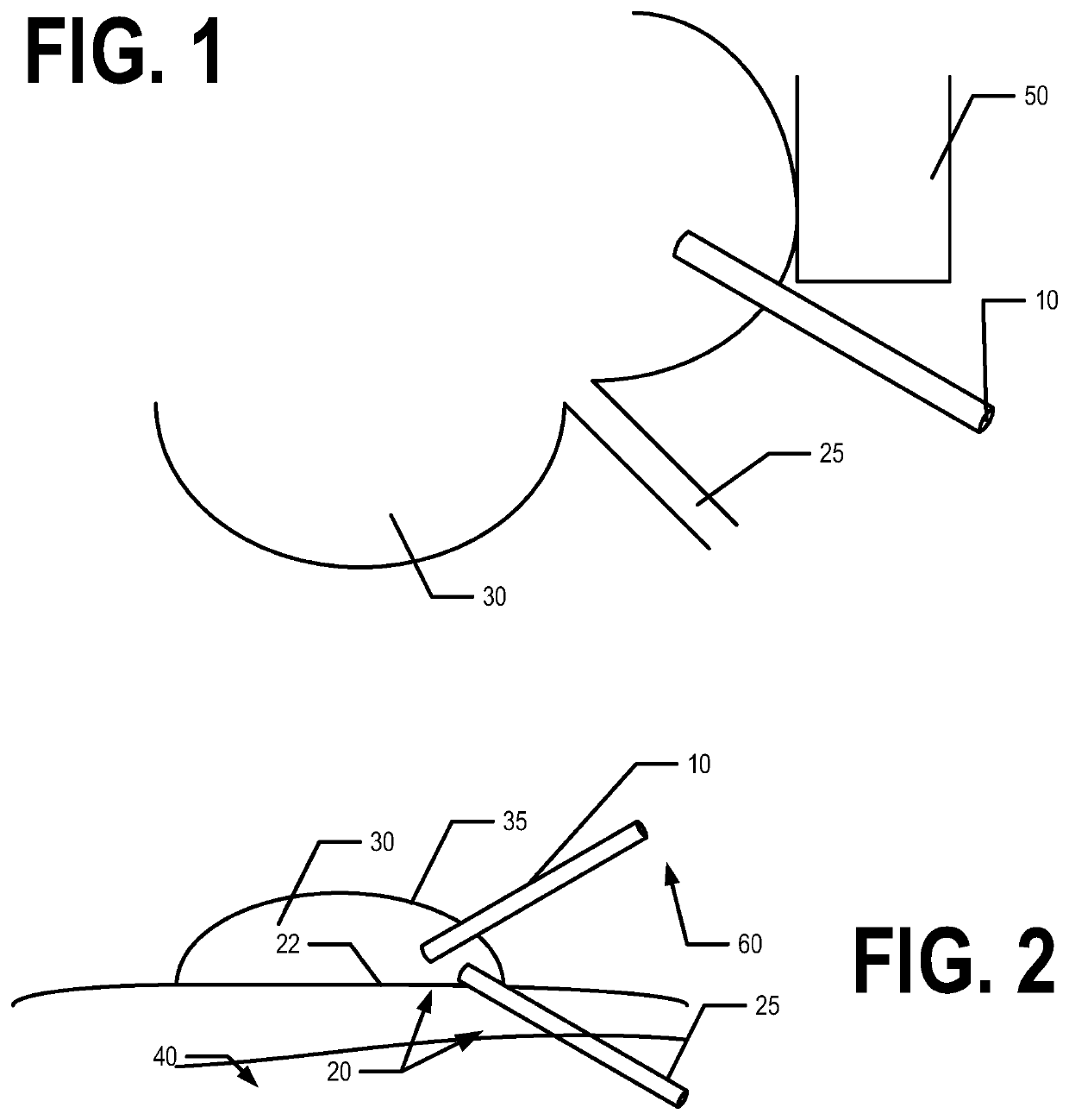
[0011]FIGS. 1 and 2 provide views of a failed glaucoma drainage device (GDD) 20 that has been made functional again though the placement of a stent implant 10 in the su...


PUM

PropertyMeasurementUnit
lengthaaaaaaaaaa
diameteraaaaaaaaaa
diameteraaaaaaaaaa

Abstract

Example embodiments provide techniques for managing and resolving failed glaucoma drainage devices (GDDs). In example embodiments, these techniques require only a simple office or minor-operating room procedure. For example, a GDD may fail due to a fibrous capsule forming about the plate portion of the GDD and preventing aqueous flowing through the tube of the GDD from the anterior region from leaving the encapsulated bleb area. The failed GDD may be made to function effectively again, in an example embodiment, by placing and / or implanting a stent implant into the wall of the fibrous capsule to allow aqueous to flow through the stent into the subconjunctival space. According to an aspect of the present invention, a method for treating a failed GDD is provided. In an example embodiment, the method comprises placing a stent implant in the wall of the capsule surrounding a posteriorly placed episcleral plate of the GDD.

Description

TECHNICAL FIELD[0001]Embodiments of the present invention relate to the drainage of failed glaucoma drainage devices (GDDs). Example embodiments provide techniques for managing and resolving failed GDDs in this respect and otherwise.BACKGROUND[0002]Approximately 15-40% of human glaucoma drainage device (GDD) implants fail to moderate an acceptable intraocular pressure (IOP) over time. For example, the GDD fails to provide sufficient drainage over an extended period of time. Currently, treatment for failed GDDs consists of either laser cyclophotocoagulation or placing a second GDD implant. Laser cyclophotocoagulation us a cyclodestructive procedure that carries the risk of long term inflammation and, if excessively done, can result in phthisis and blindness. Current therapies in cases of failed glaucoma drainage implants include (a) an additional GDD, which takes considerable time in the operating room and may not be effective in the long term, (b) a cyclodestructive procedure which ...

Claims


Application Information

Patent Timeline
Patent Type & Authority Applications(United States)
IPC IPC(8): A61F9/007A61F2/82A61K31/407A61K9/00
CPCA61K9/0019A61K9/0048A61F9/00781A61F2/82A61K31/407A61K45/06A61K2300/00
Inventor SHERWOOD, MARK B.MEYERS, CRAIG A.
Owner UNIV OF FLORIDA RES FOUNDATION INC
Learn More