
Positive Pressure Vent for a Vehicle

a technology for vents and vehicles, applied in vehicle components, vehicle heating/cooling devices, transportation and packaging, etc., can solve the problems of dust ingress into recreational vehicles such as mobile homes and caravans, and difficult access, and achieve the effect of positive interior pressur

Active Publication Date: 2020-07-09
DOMETIC APPLIANCES
View PDF0 Cites 4 Cited by
  • Summary
  • Abstract
  • Description
  • Claims
  • Application Information

AI Technical Summary

Benefits of technology

The present invention provides a positive pressure vent for a vehicle that includes an air intake port, an opening, and a cover to prevent rain from entering the vehicle. The air intake port collects air from the vehicle's motion and forms a positive pressure inside the vehicle. The opening provides a path for the collected air to enter the vehicle. The size and shape of the opening and air intake port are designed to maintain a positive interior pressure above a minimum speed. The invention helps to keep the vehicle's interior dry during use.

Problems solved by technology

When travelling in dusty environments, recreational vehicles such as mobile homes and caravans and also mining trucks suffer from dust ingress as a result of a negative pressure which develops inside the vehicle while moving.
This negative pressure inside the vehicle is due to the air currents moving around the vehicle, which cause the dusty turbulent air to enter the vehicle through ventilation apertures and general venting, which consequently deposits dust inside.
In this regard, given their position on mobile homes and caravans, they are often difficult to access and as a result, rarely opened.
A further problem with pressure hatches or scupper vents is that even if it not raining, gravel, insects and some dust enters through the vent, which is particularly problematic given the position of the vents when installed.
This is generally ineffective as it is usually impossible to cover all apertures and also is very time-consuming.
This solution can also be dangerous as when cooking gas is used and / or to leave the vents closed when inhabiting the vehicle due to potential suffocation.
This solution is particularly expensive, cumbersome, adds significant weight and is known to be not fully effective.

Method used


Image

  • Positive Pressure Vent for a Vehicle
  • Positive Pressure Vent for a Vehicle
  • Positive Pressure Vent for a Vehicle

Examples


Embodiment Construction

[0049]Exemplary embodiments of the present invention will now be described in detail with reference to the accompanying drawings. In the drawings, the same elements are denoted by the same reference numerals throughout. In the following description, detailed descriptions of known functions and configurations incorporated herein have been omitted for conciseness and clarity.

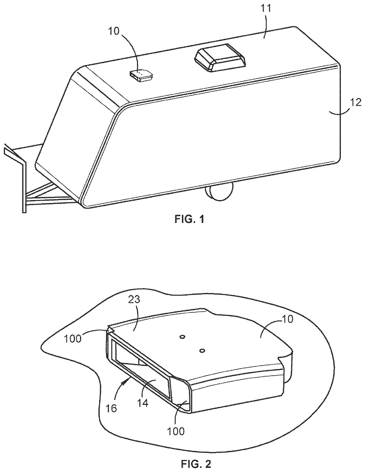
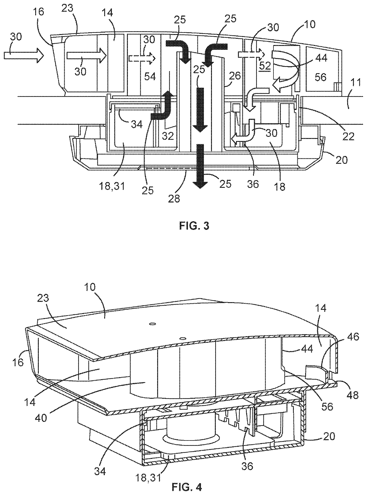
[0050]Referring to the accompanying drawings and initially to FIGS. 1 and 2, there is shown a positive pressure vent 10 for a vehicle 12 such as a caravan, recreational or mining vehicle. In the present embodiment, the vent 10 is located in the front portion of the roof 11 of a caravan, well away from turbulent flow and substantial dust at a rear of the vehicle. However, in other not shown embodiments, the pressure vent 10 may be placed in any position on a vehicle that has access to airflow due to the forward motion of the vehicle. In one alternative location, the vent may be installed in a hatch in the roof of t...


PUM


Abstract

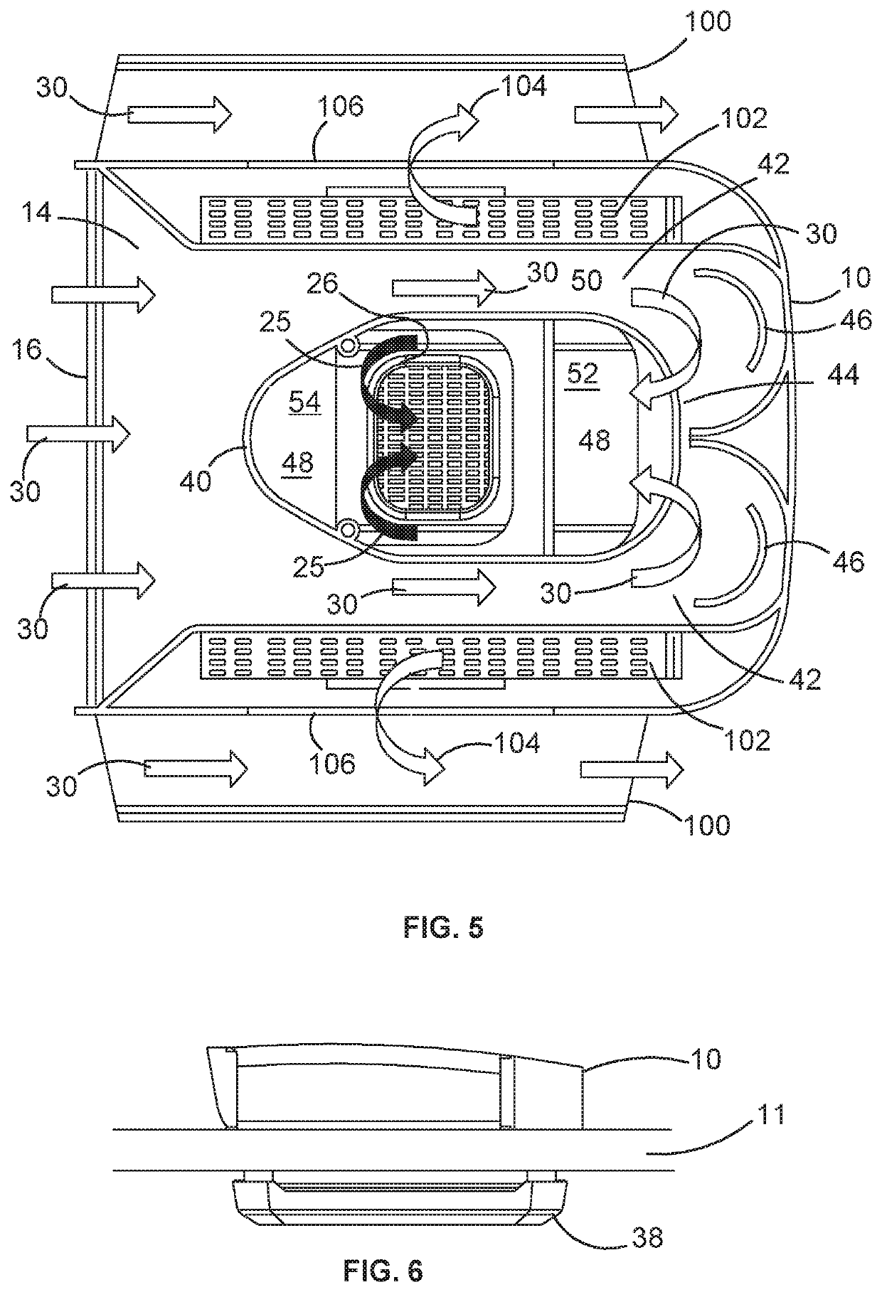
According to the invention, there is provided a positive pressure vent (10) for a vehicle (12). The vent (10) includes an inlet chamber (14) having an air intake port (16) facing into an air stream generated by motion of the vehicle (12) so as to collect air and form a positive pressure inside the inlet chamber (14). There is further provided a filter (18) adapted to filter air from the inlet chamber (14) of particulate matter. A filtered air path (25) is further provided for allowing filtered air from the filter (18) to travel to the interior of the vehicle (12) under the urging of the positive pressure from the inlet chamber (14).

Description

FIELD OF INVENTION[0001]The present relates to vents and in particular to a vent for a vehicle.[0002]The invention has been developed primarily for use as a positive pressure vent for a vehicle and will be described hereinafter with reference to this application. However, it will be appreciated that the invention is not limited to this particular field of use.BACKGROUND[0003]The following discussion of the prior art is intended to place the invention in an appropriate technical context and enable the associated advantages to be fully understood. However, any discussion of the prior art throughout the specification should not be considered as an admission that such art is widely known or forms part of the common general knowledge in the field.[0004]When travelling in dusty environments, recreational vehicles such as mobile homes and caravans and also mining trucks suffer from dust ingress as a result of a negative pressure which develops inside the vehicle while moving. This negative...

Claims


Application Information

Patent Timeline
Patent Type & Authority Applications(United States)
IPC IPC(8): B60H3/06B60H1/26
CPCB60H1/262B60H1/00364B60H3/0616B60H3/0641B60H1/00378B60H1/245B60H3/06
Inventor CHEVALIER, NICOLAS CHRISTOPHE GILLES
Owner DOMETIC APPLIANCES
Learn More