Valve assembly having improved cylindrical cam operation

Active Publication Date: 2020-06-18
KORENS
View PDF0 Cites 2 Cited by
  • Summary
  • Abstract
  • Description
  • Claims
  • Application Information

AI Technical Summary

Benefits of technology

The valve assembly described in this patent allows for stable movement of the valve seat up and down, which helps to finely adjust the flow rate of exhaust gas. It can prevent damage to the valve seat, reduce manufacturing costs, improve durability, and improve the fastening force of the magnet. The movement direction of the poppet shaft remains constant, and the valve is kept in a vertical position.

Problems solved by technology

Accordingly, there is a problem that wear of the valve seat is increased and reliability in opening and closing is reduced.
Further, when the valve seat 40 moves up and down at very high speed when closing a passage, it is difficult to finely adjust the flow rate of exhaust gas and the valve seat may be damaged by large shock that is applied to the valve seat.
Further, the valve assembly in the related art has another problem of high manufacturing cost and low durability of the bearing unit.

Method used


Image

  • Valve assembly having improved cylindrical cam operation
  • Valve assembly having improved cylindrical cam operation
  • Valve assembly having improved cylindrical cam operation

Examples


Embodiment Construction

[0033]An embodiment of a valve assembly with improved cylindrical cam operation according to the present invention is described in detail hereafter.

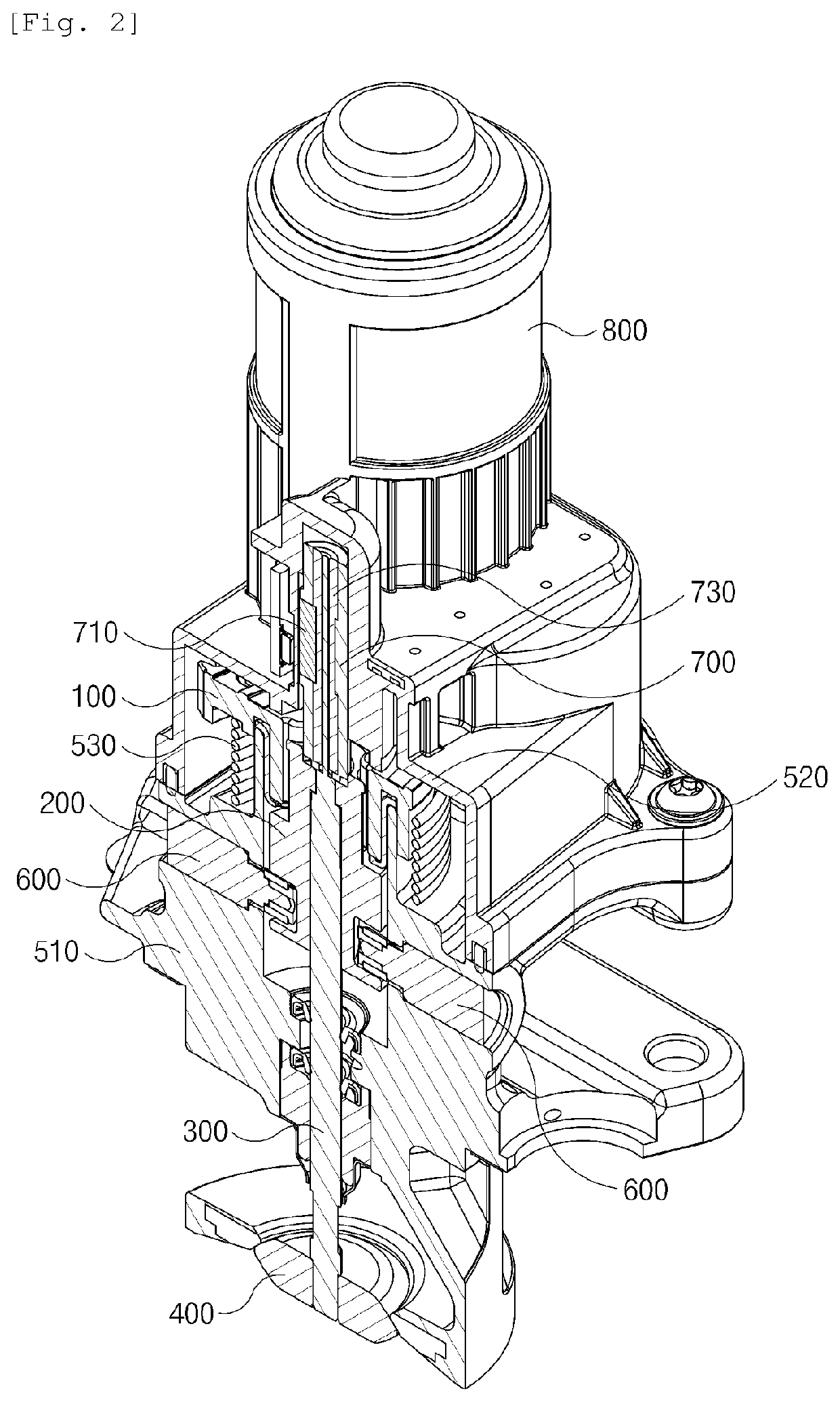
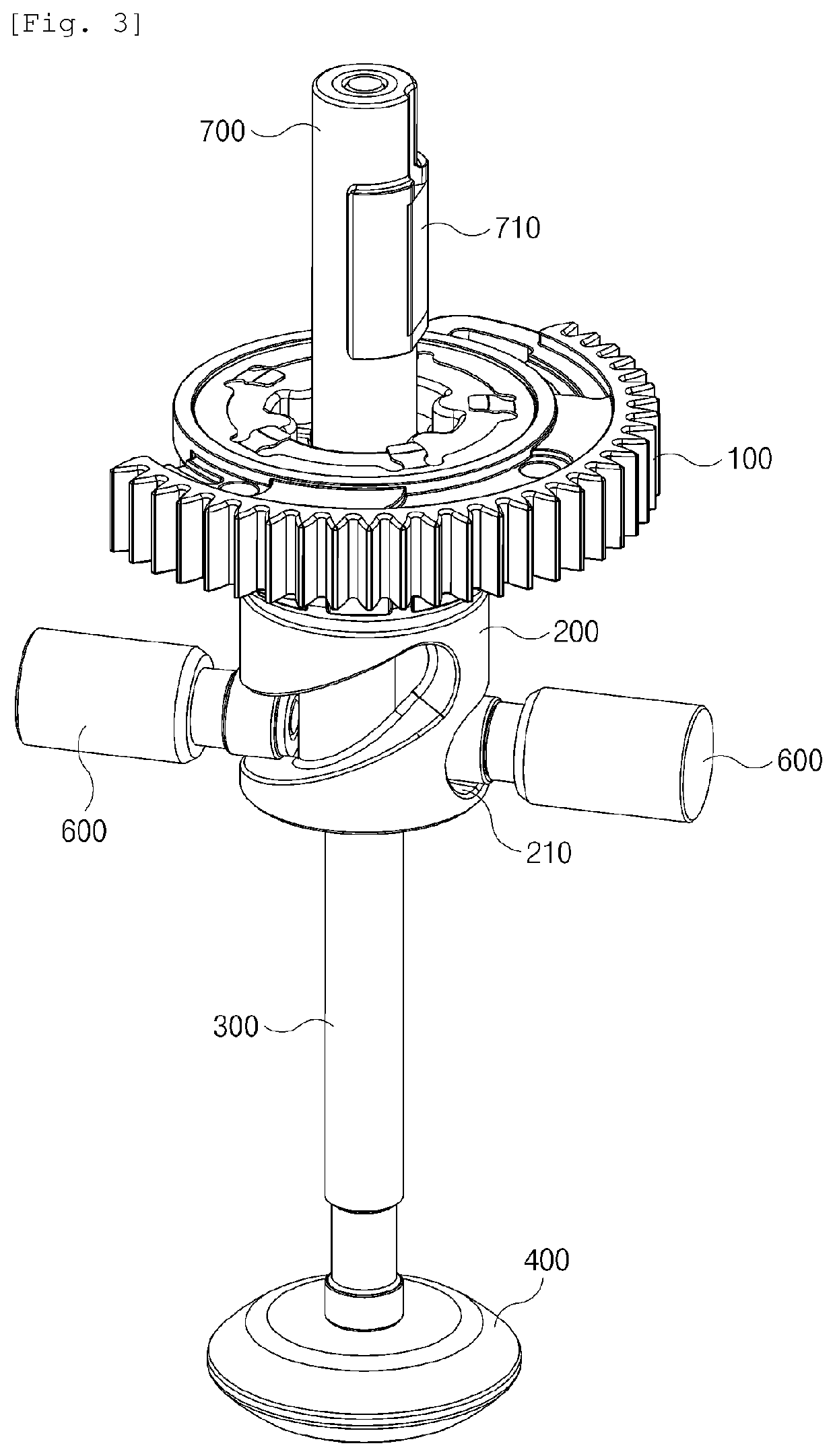
[0034]FIG. 2 is a cross-sectional perspective view showing the internal structure of a valve assembly according to the present invention and FIG. 3 is a perspective view showing a structure when a bearing unit is mounted on a cylindrical cam.

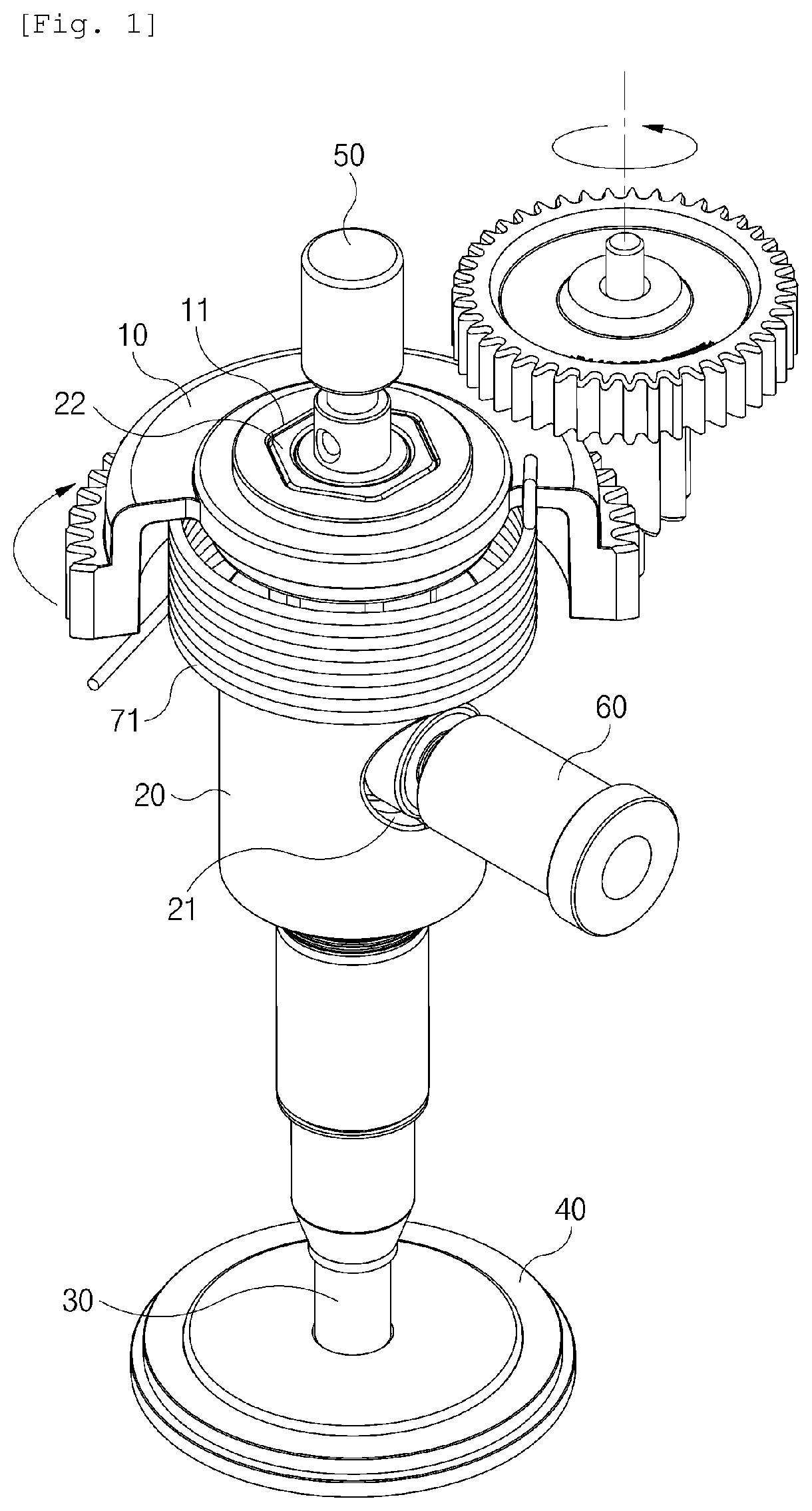
[0035]A valve assembly using a cylindrical cam 200 according to the present invention is an apparatus for moving up and down a valve seat 400 by changing torque transmitted from the outside into straight feeding force. As shown in FIGS. 2 and 3, the valve assembly includes: a rotary gear 100 being rotated about a vertical central axis that is a rotational axis by force applied from the outside, and having a non-circular insertion hole 110 on the central axis; a cylindrical cam 200 being able to move up and down while rotating integrally with the rotary gear 100 with an upper end thereof inserted in t...


PUM


Abstract

A valve assembly includes: a rotary gear being rotated about a vertical central axis that is a rotational axis by force from an outside, and having a non-circular insertion hole on the central axis; a cylindrical cam being able to move up and down while rotating integrally with the rotary gear with an upper end thereof inserted in the insertion hole, and having two or more inclined slide grooves on an outer side thereof; a poppet shaft disposed through the rotational axis of the cylindrical cam to be able to move up and down integrally with and rotate independently from the cylindrical cam; a valve seat coupled to a lower portion of the poppet shaft; a housing and a cover that surround the cylindrical cam; and two or more bearing unit each having a first side fixed to the housing and having second sides respectively inserted in the slide grooves.

Description

TECHNICAL FIELD[0001]The present invention relates to a valve assembly that moves up and down a valve seat by changing a rotation motion into a straight motion using a cylindrical cam and, more particularly, to a valve assembly in which the operation of a cylindrical cam is improved such that the cylindrical cam can more smoothly change a rotary motion into a straight motion without inclining to a side.BACKGROUND ART[0002]In general, the exhaust gas of vehicles is gas that is discharged to the atmosphere through an exhaust manifold after fuel is compressed and expanded at high temperature and high pressure in a cylinder. Most of the exhaust gas is vapor and carbon dioxide, and noxious substances such as carbon oxide (CO), hydrocarbon (HC), nitrogen oxide (NOx) are included.[0003]An Exhaust Gas Recirculation System (EGR), which is a device that reduces nitrogen oxide of exhaust gas, reduces the production amount of nitrogen oxide (NOx) by decreasing combustion temperature when a gas ...

Claims


Application Information

Patent Timeline
IPC IPC(8): F02D41/00F02M26/68F16K31/524F16K31/53
CPCF02D41/0077F02M2026/005F02D41/0065F02M26/68F02D41/0027F16K31/524F16K31/53F02D41/005F02M26/67F16K31/52408F16K31/528F02M26/66F02M26/72F02M26/54F16K31/5286
Inventor CHO, HYUNG GEUN
Owner KORENS
Why Eureka
Try Eureka