X-ray device and method of applying x-ray radiation

a technology of x-ray radiation and x-ray tube, which is applied in the direction of x-ray tube cooling, x-ray tube anode cooling, x-ray tube cooling, etc., can solve the problems of small angle of incidence of x-ray radiation and accompanying lowering radiation intensity, so as to improve the life of the converter and increase the amount of x-ray radiation. , the effect of improving the lifetime of the converter

Active Publication Date: 2020-06-11
SIEMENS HEALTHCARE GMBH
View PDF0 Cites 6 Cited by
  • Summary
  • Abstract
  • Description
  • Claims
  • Application Information

AI Technical Summary

Benefits of technology

[0018]According to a further embodiment, the x-ray device includes a cooling device configured to cool the converter. This allows even better dissipation of heat away from the converter, advantageously improving the lifetime of the converter.
[0019]According to a further embodiment, the converter is arranged inside the transmission body. In that configuration, the converter may be arranged especially close to the anode, advantageously increasing the amount of x-ray radiation produced by the anode converted into monochromatic x-ray radiation by the converter.
[0020]According to a further embodiment, the converter is arranged in a curved form such that at least one lateral edge of the converter is in contact with the anode. This advantageously increases the amount of x-ray radiation produced by the anode converted into monochromatic x-ray radiation by the converter even further.
[0021]According to a ...

Problems solved by technology

This leads to generally small angles of incidence of the x-ray radiation and accompanying lowered intensity of radiation as...

Method used


Image

  • X-ray device and method of applying x-ray radiation
  • X-ray device and method of applying x-ray radiation
  • X-ray device and method of applying x-ray radiation

Examples


Embodiment Construction

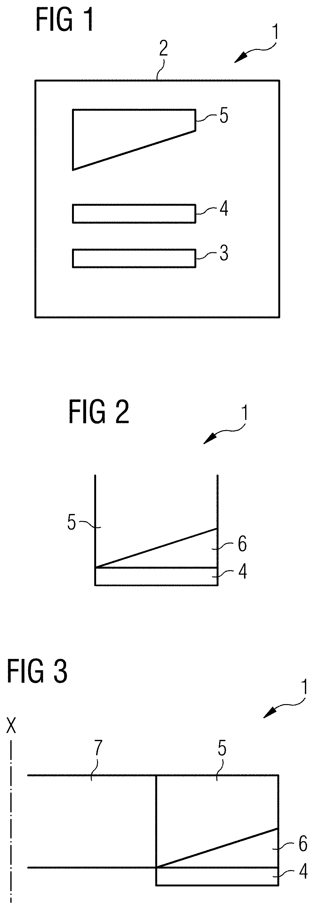
[0039]FIG. 1 shows a schematic representation of an embodiment of an x-ray device 1. The x-ray device includes a housing 2, a cathode 3, an anode 4, and a converter 5. The housing 2 is airtight and configured to provide a vacuum therein. The cathode 3, the anode 4, and the converter 5 are arranged inside the housing 2. The anode 4 is arranged between the cathode 3 and the converter 5.

[0040]In use, the cathode 3 emits electrons into the vacuum inside the housing 2, for example, through the field emission effect, thermionic emission, or other well-known physical processes. Under effect of the electrical field between the cathode 3 and the anode 4, the electrons are accelerated towards the anode 4. Upon impacting on the anode 4, the electrons interact with the anode 4 and thereby produce x-ray radiation through bremsstrahlung, characteristic x-ray emission, or the like. The anode 4 is configured to produce x-ray radiation in transmission, which means that the produced x-ray radiation r...


PUM


Abstract

The present disclosure provides an x-ray device including a housing configured to provide a vacuum therein, a cathode arranged inside the housing and configured to emit electrons, an anode arranged inside the housing and configured to produce x-ray radiation when impacted by electrons emitted by the cathode, and a converter configured to convert the x-ray radiation produced by the anode into monochromatic x-ray radiation, wherein the anode is configured to produce x-ray radiation in transmission and is arranged between the cathode and the converter. The present disclosure may be used in medical imaging, therapy, spectroscopy, and the like. Geometries and configurations may be improved compared to previously known x-ray devices when it comes to requirements for space, materials used, complexity of electrical wiring, distance between cathode and anode, and providing supplementary functions.

Description

[0001]The present patent document claims the benefit of U.S. Provisional Patent Application No. 62 / 777,043, filed Dec. 7, 2018, which is hereby incorporated by reference in its entirety. The present patent document also claims the benefit of European Patent Application No. 19195781.0, filed Sep. 6, 2019, which is also hereby incorporated by reference.TECHNICAL FIELD[0002]The present application is directed to an x-ray device and a method of applying x-ray radiation.BACKGROUND[0003]X-ray radiation is being used in a multitude of applications, ranging from medical imaging or therapy or security checks at airports to crystallography. The most common devices for generating x-ray radiation are x-ray tubes, which are vacuum tubes in which electrons are emitted by a cathode and accelerated towards an anode, where the electrons produce x-ray radiations through bremsstrahlung or other physical processes. X-ray tubes are generally simpler in construction and use than other ways of producing x...

Claims


Application Information

Patent Timeline
IPC IPC(8): H05G1/02H05G1/04H01J35/10
CPCH05G1/025H01J2235/08H01J35/105H01J2235/1204H05G1/04H01J35/10H01J2235/1295H01J35/116
Inventor FREUDENBERGER, JÖRGFRITZLER, ANJAGEITHNER, PETERHACKENSCHMIED, PETERWEBER, THOMAS
Owner SIEMENS HEALTHCARE GMBH
Why Eureka
Try Eureka