
Image display apparatus, image display method, and storage medium

Inactive Publication Date: 2020-06-11
KONICA MINOLTA INC
View PDF17 Cites 0 Cited by
  • Summary
  • Abstract
  • Description
  • Claims
  • Application Information

AI Technical Summary

Benefits of technology

The invention aims to provide an image display system that allows users to quickly and easily check results from dynamic imaging and improve diagnosis efficiency. This can be useful for regions that change over time, like the diaphragm, which can be easily visualized through multiple images taken at different times.

Problems solved by technology

However, one time of dynamic imaging usually generates dozens or hundreds of images, which requires much time just to check the change.
Furthermore, because a doctor views the images as an animation, the doctor finds it difficult to check the change by one time of viewing, and may overlook the change.
Because of such difficulty in visually checking movement of the target region, the doctor consumes much time to view the images for making diagnosis.

Method used


Image

  • Image display apparatus, image display method, and storage medium
  • Image display apparatus, image display method, and storage medium
  • Image display apparatus, image display method, and storage medium

Examples


Embodiment Construction

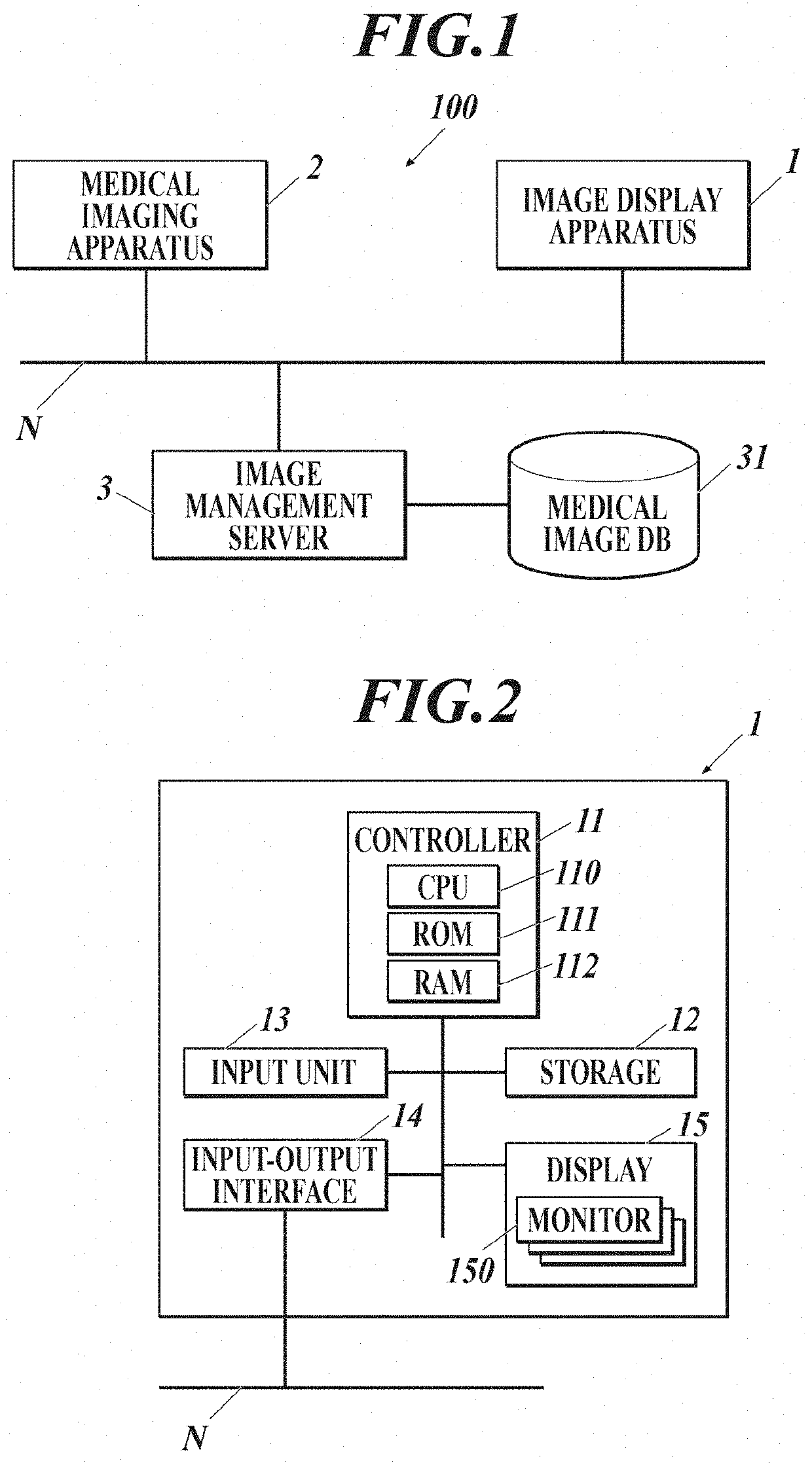
[0027]Hereinafter, one or more embodiments of an image display apparatus (image display system) according to the present invention will be described with reference to the drawings.

[0028]The following is a case where one apparatus (image display apparatus) includes: a controller 11 that analyzes images, controls displaying, and determines a range of medical images to be displayed; a storage 12; and a display 15 (all shown in FIG. 2), which are described below. The image display apparatus described below can be configured as an image display system. For example, it is possible to configure some or all of parts / components including a functional part analyzing images, a functional part determining a range of medical images to be displayed, a storage, and a display as individual apparatuses, and connect them as a system (i.e. image display system, not illustrated) on a network.

[0029]Although the embodiments described below have various limitations that are technically preferable to embod...


PUM


Abstract

An image display apparatus includes an image obtainer, a hardware processor, and a display. The image obtainer obtains a plurality of medical images of a same target region taken through serial radiography along a time axis. The hardware processor generates a display image based on the medical images obtained by the image obtainer. The display displays the display image generated by the hardware processor. The hardware processor combines the medical images into one composite medical image as the display image.

Description

CROSS-REFERENCE TO RELATED APPLICATION[0001]The present invention claims priority under 35 U.S.C. § 119 to Japanese Patent Application No. 2018-229568, filed on Dec. 7, 2018, the entire contents of which are incorporated herein by reference.BACKGROUND1. Technological Field[0002]The present invention relates to an image display apparatus, an image display method, and a storage medium.2. Description of the Related Art[0003]There have been attempts to utilize, for diagnosis, a dynamic image of a region of a body to be diagnosed (hereinafter called a target region) taken with a semiconductor image sensor, such as an FPD (flat panel detector), instead of or in addition to conventional radiological (X-ray) still images taken with a film / screen or a photostimulable phosphor plate.[0004]More specifically, by making use of high responsivity of a semiconductor image sensor in reading / deleting image data, a dynamic image of a target region is taken by continuously emitting pulsed radiation fro...

Claims


Application Information

Patent Timeline
IPC IPC(8): A61B6/00G06T7/00
CPCG06T2207/10016G06T2207/30061A61B6/5235G06T2207/20212G06T2207/10116G06T7/0016G06T7/12G06T11/00A61B6/465A61B6/469A61B6/54
Inventor NANJO, TAKAFUMI
Owner KONICA MINOLTA INC
Learn More