Solar panel mounting system and method

a solar panel and support structure technology, applied in the direction of photovoltaic supports, heat collector mounting/supports, light and heating equipment, etc., can solve the problems of falling off the roof, difficult retrieval, accidental dislodge of clips, etc., and achieve the effect of rapid installation of solar panels

Active Publication Date: 2020-05-28
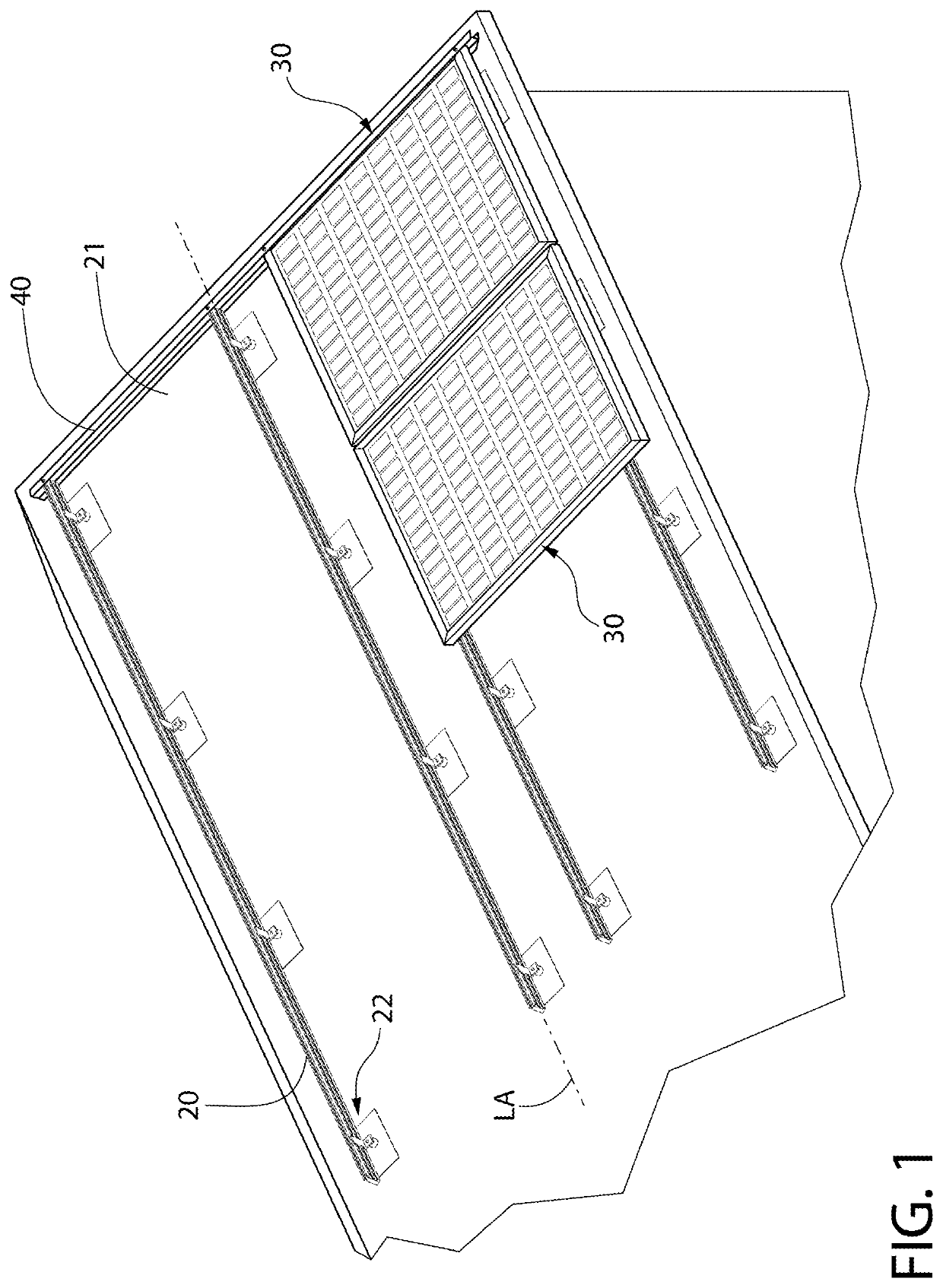
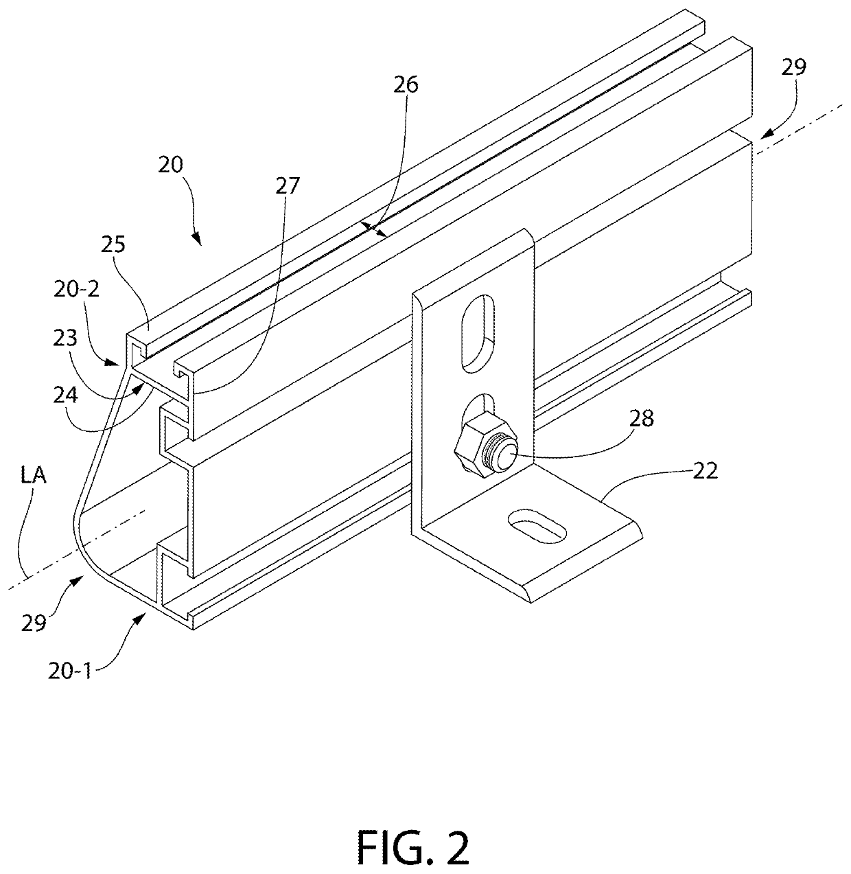
SOLAROFF SYST LLC
View PDF0 Cites 7 Cited by
  • Summary
  • Abstract
  • Description
  • Claims
  • Application Information

AI Technical Summary

Benefits of technology

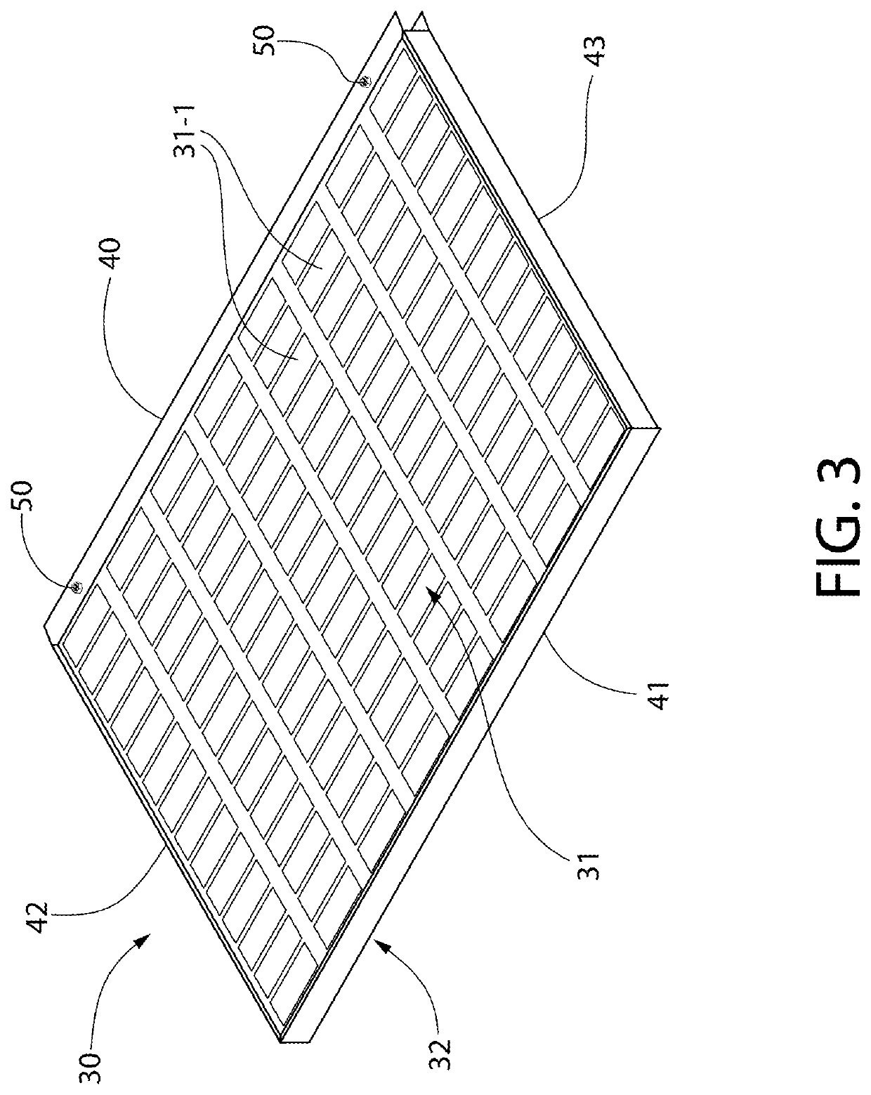
The present invention is a solar panel mounting system and method that overcomes the difficulties and risks of previous installation techniques. The system includes pre-routed conductive cabling, a snap-in rodent-proof metal conduit cover, and a frame design that reduces installation time, materials, and labor requirements. The frame design also eliminates the risk of damage to the electrical system and reduces the need for additional parts and labor. Additionally, the solar panel mounting system improves safety and provides greater income potential from solar arrays. The ultimate result is a safer, more efficient, and cost-effective solar panel mounting system.

Problems solved by technology

It is easy to accidentally dislodge the clips that are resting on the rail while waiting to be tightened, and it is not uncommon for clips to dislodge.
Often the clips slide down the roof slope and lodge themselves under previously installed modules making retrieval difficult, slide into a rain gutter, or fall off the roof entirely.
The clips are often lost in shrubbery or lawns, and can damage decks, furniture, or worst case hit someone working or walking below.
In short, this is an absurdly inefficient and cumbersome process, requiring additional installers and materials, results in wasted time expended, and creates issues of worker safety.
Also during the foregoing standard process of securing the next adjacent mating panel to the horizontally-oriented support rail, cable management can be problematic.
This can be difficult on a pitched “A” frame roof as the panel will want to slide downward due to gravity until the fastener is firmly tightened as explained above.
This adds a significant amount of time to the installation as the clips must very tightly grip the panel frame.
In addition, the cables remain largely exposed beneath the solar panels after installation creating yet another problem.
Since these electrical cables can carry currents up to 1000 volts DC, chewed or even just nibbled electrically conductive cabling can be lethal to service personnel if touched.
Even with redundancy in electrical grounding of the solar array, the module frames and rails can further become energized by damaged power cables posing danger.
Furthermore, the exposed conductive cabling can short and spark causing fires.
Finally, if the system is no longer capable of providing electricity, the strings are interrupted and the inverter senses a fault, short or interruption, and turns off instantly, thereby rendering the system non-functional.
This is difficult and dangerous work preformed while on the roof.

Method used


Image

  • Solar panel mounting system and method
  • Solar panel mounting system and method
  • Solar panel mounting system and method

Examples


Embodiment Construction

[0032]The features and benefits of the invention are illustrated and described herein by reference to example (“exemplary”) embodiments. This description of example embodiments is intended to be read in connection with the accompanying drawings, which are to be considered part of the entire written description. Accordingly, the disclosure expressly should not be limited to such embodiments illustrating some possible non-limiting combination of features that may exist alone or in other combinations of features.

[0033]In the description of embodiments disclosed herein, any reference to direction or orientation is merely intended for convenience of description and is not intended in any way to limit the scope of the present invention. Relative terms such as “lower,”“upper,”“horizontal,”“vertical,”, “above,”“below,”“up,”“down,”“top” and “bottom” as well as derivative thereof (e.g., “horizontally,”“downwardly,”“upwardly,” etc.) should be construed to refer to the orientation as then descr...


PUM


Abstract

A solar panel mounting system for forming a solar array includes longitudinal support rails mounted to a support structure such as a roof. A first solar panel disposed on the rails has a peripheral frame including a locking frame member with deformable clamping portion configured for slideably receiving a peripheral frame portion of an adjacent second solar panel. A pair of captive T-bolt sets passing through the clamping portion include T-bolts having locking heads and nuts frictionally engaged with the T-bolts to rotate the T-bolts. The heads are each inserted and rotationally locked into fastening channels of respective support rails. The second solar panel is inserted into the first panel clamping portion and the nuts are fully tightened producing a clamping action which locks the first and second panels together. Power / control cables may be routed inside covered cable compartments on rears of the panels for protection against rodent damage.

Description

CROSS-REFERENCE TO RELATED APPLICATIONS[0001]The present application claims the benefit of priority to U.S. Provisional Application No. 62 / 771,642 filed Nov. 27, 2018, which is incorporated herein by reference in its entirety.BACKGROUND OF THE INVENTION[0002]The present invention generally relates to solar panel systems, and more particularly to a system and related method for mounting a solar array on a support structure.[0003]The most common method of mounting solar modules (panels) to a support structure such as a rooftop starts with mounting extruded aluminum main runners or rails horizontally across the roof using “L” brackets. The main rails provide the backbone for mounting the individual solar panels to the roof or other support structure. The solar panels, which are typically of rectangular planar construction, are mounted across at least two main rails for support from underneath.[0004]The solar panels are typically secured in position on the main rails via individually pa...

Claims


Application Information

Patent Timeline
Patent Type & Authority Applications(United States)
IPC IPC(8): H02S30/10F24S25/35F24S25/40F24S25/61H02S40/36H02S20/23
CPCF24S25/61F24S25/35F24S2025/6006H02S30/10H02S20/23F24S25/40H02S40/36F24S25/20F24S25/33F24S2025/801F24S2025/807F24S25/63F24S2020/12F24S2025/6003
Inventor KOCH, STUARTCOSTANZA, JON
Owner SOLAROFF SYST LLC
Why Eureka
Try Eureka