
Spark containment cap

Pending Publication Date: 2020-05-28
AIRBUS OPERATIONS LTD
View PDF4 Cites 0 Cited by
  • Summary
  • Abstract
  • Description
  • Claims
  • Application Information

AI Technical Summary

Benefits of technology

The invention relates to a cap that can be used to seal the end of a fastener on a structure. The cap has a base rim that is positioned close to the surface of the structure, minimizing leakage of air and sealant. The cap also has an engaging feature that helps locate the base rim and a mating feature that allows for easy placement of the cap. The distribution of uncured sealant can be controlled, resulting in an even flow of sealant around the cap. These features make the sealing process easier and more efficient.

Problems solved by technology

There is therefore a high probability of lightning attachment at any of the many metallic fasteners in the exterior surface, which have a much lower electrical resistance.
The skirt may impair location of the nut cap relative to other features.

Method used


Image

  • Spark containment cap
  • Spark containment cap
  • Spark containment cap

Examples


Embodiment Construction

)

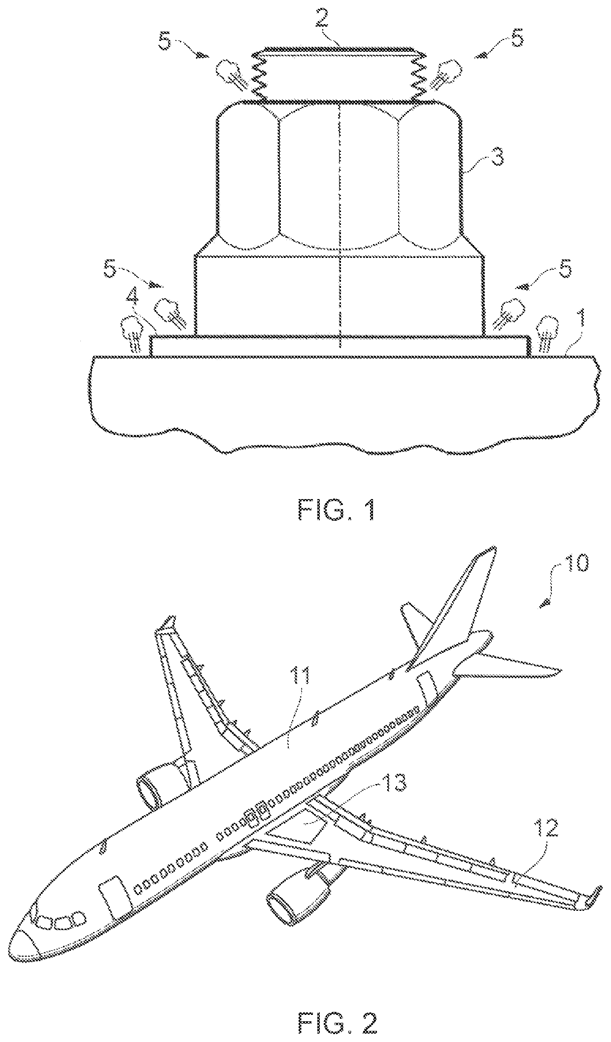
[0057]An aircraft 10 is shown in FIG. 2. The aircraft 10 includes a fuselage 11. Two wings 12 extend from the fuselage 11. It will be appreciated that the fuselage 11 and wings 12 may take a variety of different planform shapes and profiles depending on the particular application. Fuel tanks 13 are formed in the fuselage 11 and wings 12. One such fuel tank 13 is shown schematically in FIG. 2. The fuel tanks 13 are formed by a structure or structures forming part of the aircraft 10.

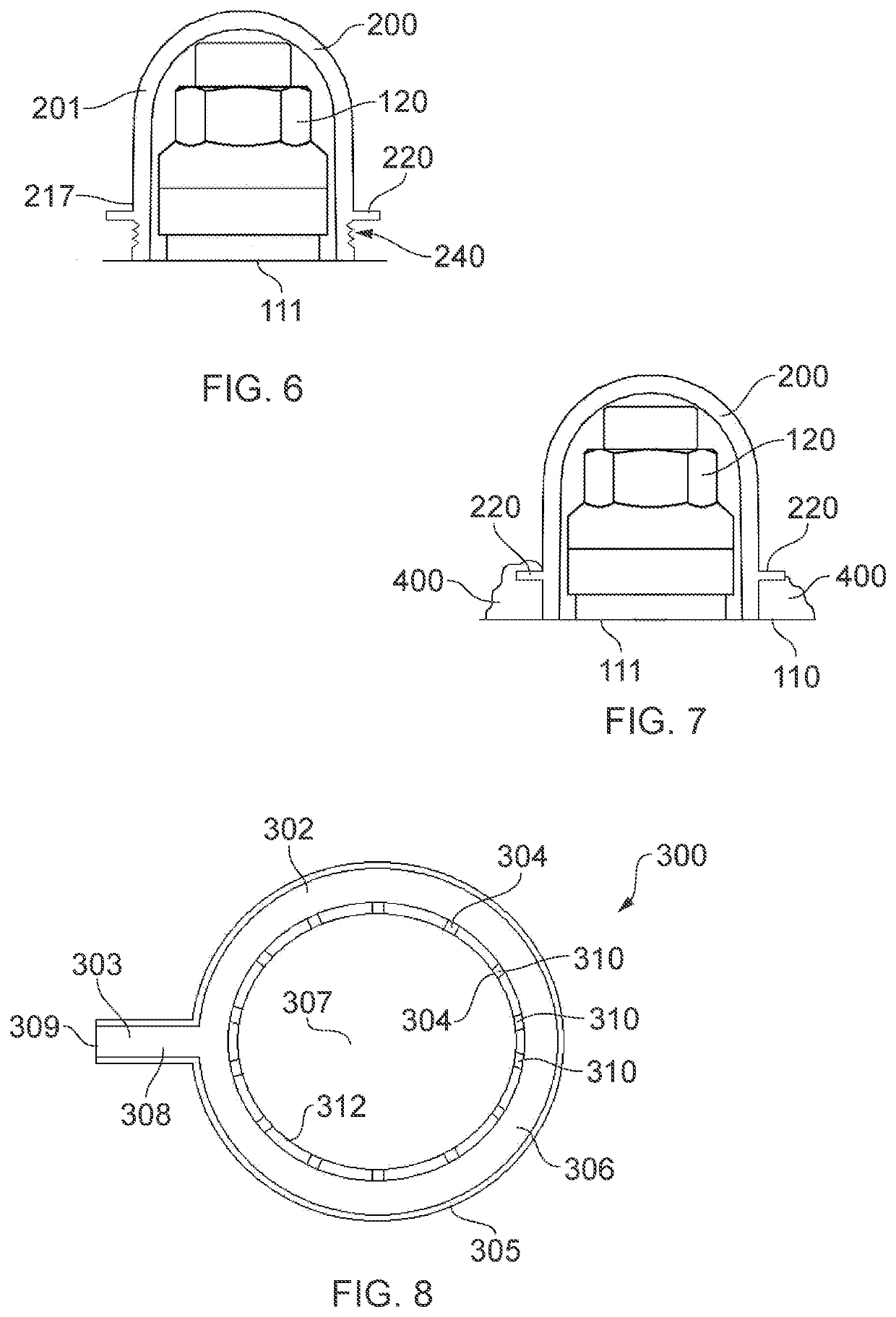
[0058]FIGS. 3 and 7 show a joint 100 in stages of installation. A cap 200 of the joint 100 is shown in FIG. 4. The joint 100 is shown assembled in FIG. 7. The joint 100 comprises a structure 110 such as an aircraft skin panel. The structure 110 has a planar surface 111. A fastener 120 extends through the structure 110. The structure 110 in this embodiment is a composite aircraft structural component, but may be a hybrid composite-metallic or other component.

[0059]The structure 110 may include structural f...


PUM

PropertyMeasurementUnit
Diameteraaaaaaaaaa
Resilienceaaaaaaaaaa

Abstract

A spark prevention cap is disclosed. The cap forms a sealed cavity around an end of a fastener protruding from a surface of a structure, for example, an aircraft structure. The cap has a cap body with an annular base terminating at a rim. The rim surrounds an opening into a central cavity for receiving the end of the fastener. The annular base has an external circumferential surface extending from the base rim, and a mating feature on the external circumferential surface configured to contact a sealant material applied externally to the cap.

Description

FIELD OF THE INVENTION[0001]The present invention relates to a spark containment cap for forming a sealed cavity around an end of a fastener. The present invention also relates to a joint, a method of assembling a joint, an aircraft comprising at least one of the cap and the joint, a spark prevention cap installation system, and a method of forming a sealed cavity around an end of a fastener.BACKGROUND OF THE INVENTION[0002]Large passenger aircraft are typically struck by lightning once or twice a year, each lightning bolt striking with up to 200,000 amps of electrical current that seeks the path of least electrical resistance. Many modern passenger aircraft have exterior surfaces made from composite materials which have a very high electrical resistance. There is therefore a high probability of lightning attachment at any of the many metallic fasteners in the exterior surface, which have a much lower electrical resistance. In the wing, some of these fasteners pass through the outer...

Claims


Application Information

Patent Timeline
IPC IPC(8): B64D45/02F16B37/14
CPCB64D45/02F16B37/14F16B33/004B05C17/00516B05C5/0291B29C45/14336B29C45/14467
Inventor MONAGHAN, THOMAS
Owner AIRBUS OPERATIONS LTD
Learn More